Introduction
A wiring diagram audio mobil serves as the definitive technical blueprint for integrating aftermarket head units, amplifiers, and speaker systems into a vehicle’s native electrical architecture. According to SAE J1128 automotive wiring standards, low-tension primary cable must be selected based on current capacity and environmental exposure to prevent thermal degradation within the chassis harness. Mastery of these diagrams is essential for maintaining electrical integrity, preventing short circuits, and ensuring compatibility between OEM signal outputs and aftermarket audio components. Accessing precise schematics through Audio and Entertainment Wiring Diagrams remains the foundational step for any successful mobile electronics installation.
Wiring Technical Snapshot:
- Core Focus: Mapping signal, power, ground, and illumination paths in vehicle audio systems.
- Target Scope: Automotive 12V DC systems, specifically head unit integration and amplifier power distribution.
- Key Recommendation: Always verify factory wire colors with a digital multimeter rather than relying solely on generic color charts.
Core Principles and Detailed Overview
Wiring diagram audio mobil documentation provides a systematic visualization of signal flow and power distribution required to interface external audio hardware with a vehicle’s existing wiring harness. These diagrams categorize circuits into three primary groups: power (constant 12V, switched accessory, and illumination), ground (chassis or dedicated return), and signal (speaker outputs and RCA low-level inputs). Understanding the difference between high-level (amplified) and low-level (pre-amp) signals is critical to avoid impedance mismatches that lead to clipping or hardware failure. Technicians must utilize Wiring Diagram Basics to interpret symbolic representations of relays, fuses, and connectors, ensuring that every modification adheres to the vehicle’s electrical load limitations.
Key Specifications and Breakdown
| Circuit / Terminal | Standard Wire Color / Gauge | Operational Role & Safety Check |
|---|---|---|
| Constant 12V (Battery) | Yellow / 12-16 AWG | Maintains memory; verify 12.6V with DMM. |
| Switched (Accessory) | Red / 16-18 AWG | Triggers ignition-on power; check for 0V at off. |
| Chassis Ground | Black / 12-16 AWG | Completes circuit; ensure <0.5 ohm to chassis. |
Overcurrent protection must be installed as close to the power source as possible to minimize the risk of electrical fire in the event of a short circuit. — National Fire Protection Association (NFPA) 70 (NEC) Automotive/Mobile Installation Guidelines
Step-by-Step Practical Application and Guidelines
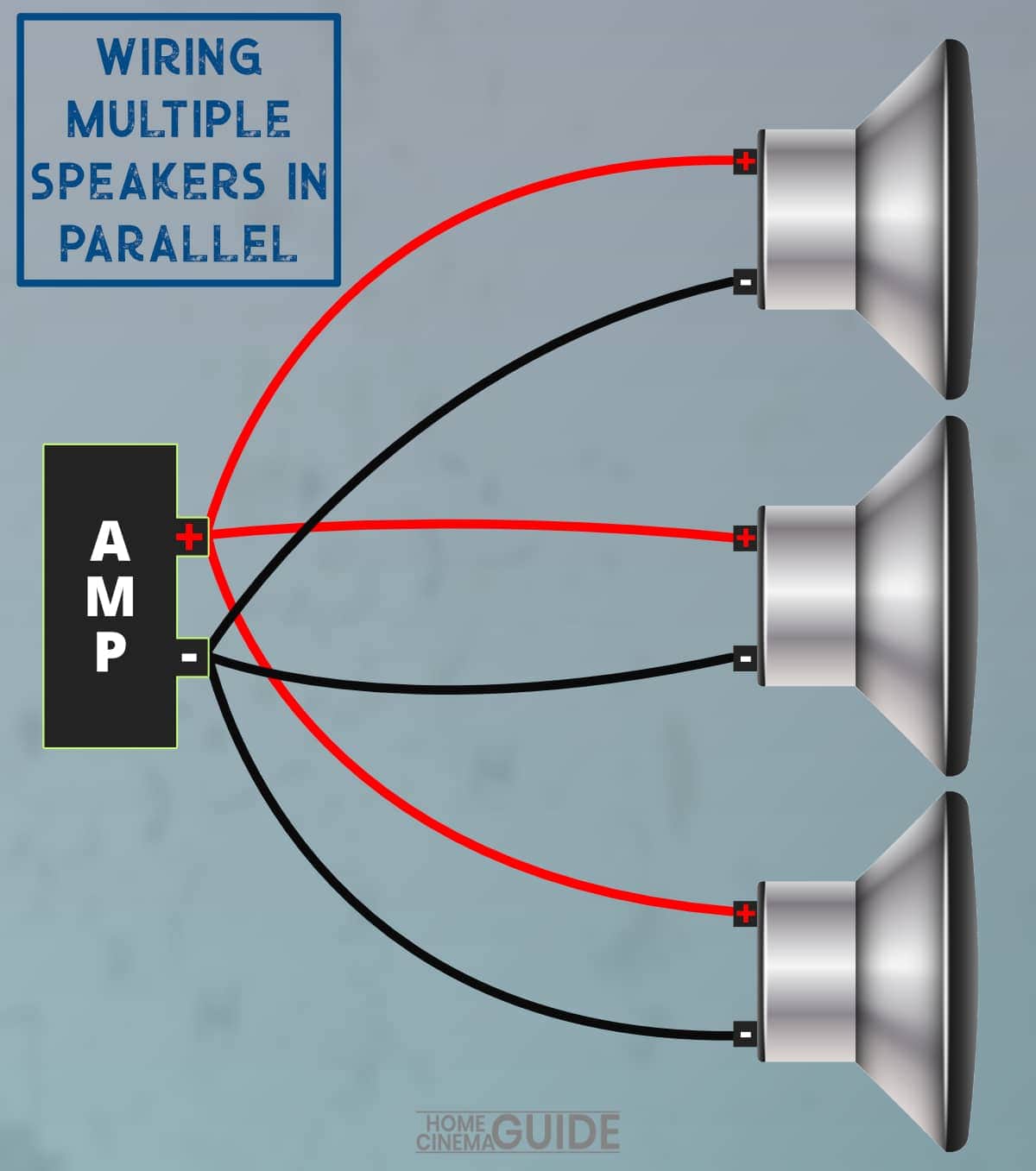
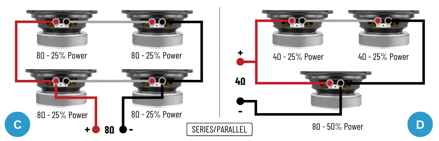
Effective implementation of a wiring diagram audio mobil requires a methodical verification process before any permanent connections are made. Begin by isolating the factory harness and identifying the constant 12V, accessory, and ground wires using a calibrated digital multimeter. Once identified, cross-reference these findings with the specific vehicle schematic found in Vehicle Wiring Diagrams to confirm pinout accuracy. After establishing the power and ground foundation, proceed to map speaker channels, ensuring positive and negative polarities are consistent across all drivers to prevent phase cancellation. Finally, conduct a continuity test across all crimped or soldered joints to ensure low resistance and mechanical stability before securing the harness with automotive-grade electrical tape or heat-shrink tubing.
Common Challenges and How to Avoid Them
Diagnostic errors in mobile audio wiring typically stem from improper grounding techniques and the failure to account for CAN-bus integration. Avoid common pitfalls by ensuring all ground connections are made to clean, unpainted metal surfaces on the vehicle chassis, as high-resistance grounds frequently cause engine noise (whine) in the audio signal. Furthermore, utilize appropriate interface modules when working with modern vehicles that utilize digital data busses for accessory power, as direct-wiring into these circuits can trigger diagnostic trouble codes (DTCs) or damage sensitive electronic control units. Regular consultation with Wiring Troubleshooting resources is advised when encountering intermittent signal loss or component failure during the installation process.
💬 Frequently Asked Questions
Explore More Wiring Diagrams and Schematics on ReadWires
Comprehensive electrical mastery requires consistent practice and access to reliable data. Whether working on complex Relay and Component Wiring Diagrams or troubleshooting simple 12V circuits, the library at ReadWires.com provides the technical foundation necessary for professional-grade results. Utilize these resources to maintain safety and performance in every automotive audio project.
Wiring Diagram Schematics & Details