Introduction
A two-way lighting circuit allows a single luminaire or group of lights to be controlled independently from two separate locations, commonly utilized in hallways, stairwells, and large rooms. Mastering this layout requires learning how to draw and explain the wiring diagram for a two way lighting circuit, ensuring that control paths remain continuous without creating short circuits. Understanding this schematic prevents installation errors, reduces troubleshooting time, and guarantees compliance with regional electrical safety mandates such as those outlined in the National Electrical Code (NEC/NFPA 70) in the United States, the Canadian Electrical Code (CEC), BS 7671 in the United Kingdom, or AS/NZS 3000 in Australia. For those exploring more residential layouts, additional references are available under Home Electrical Wiring Diagrams.
💡 Technical Key Takeaways:
- Core Focus: Diagnostic schematic and terminal connection layout for Draw And Explain The Wiring Diagram For A Two Way Lighting Circuit.
- Target Scope: Field technicians, automotive DIYers, and residential/commercial electricians.
- Safety Rule: Always disconnect the primary power source/battery terminal and verify zero voltage with a multimeter before touching wires.
Core Concepts and Wiring Fundamentals
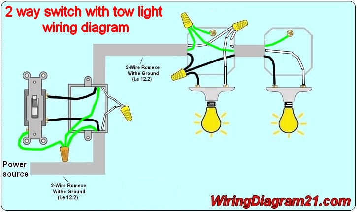
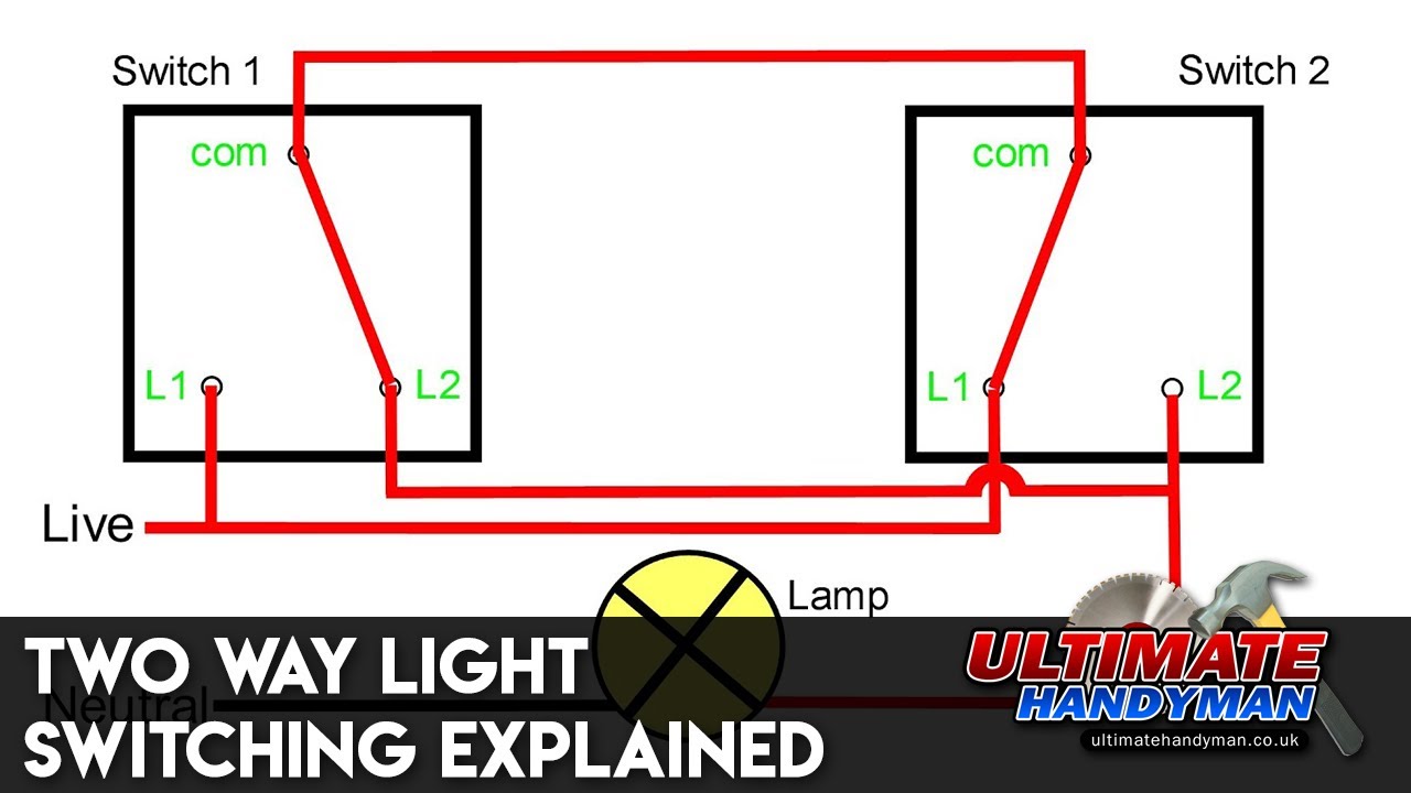
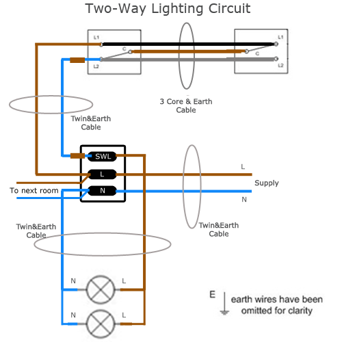
Controlling a single load from two distinct points requires specialized hardware known as three-way switches in North America or two-way switches in the UK, Australia, and Europe. Each device features three distinct terminal connections: one common terminal and two traveler terminals. Power enters the system via the supply cable, routing the ungrounded conductor (hot wire) directly to the common terminal of the first switch. Two traveler wires then bridge the corresponding traveler terminals between the first and second switches. Finally, the common terminal of the second switch carries the switched hot output onward to the lighting load.
Neutral conductors and equipment grounding conductors bypass the switching devices entirely. The neutral completes the return path from the lighting fixture back to the service panel, while the grounding conductor bonds all metallic enclosures, switch frames, and light fixtures to earth ground. Color coding varies significantly by jurisdiction. North American installations utilize black or red for hot conductors, white for neutral, and bare copper or green for ground. Conversely, UK and international systems governed by CENELEC standards employ brown for live, blue for neutral, and green-and-yellow for earth. Technicians must always verify local regulatory standards before cutting or terminating conductors.
[Electrical Safety Finding] — According to the Electrical Safety Foundation International (ESFI), residential electrical fires and thermal incidents are frequently traced back to loose terminal connections and improper wire sizing.
Diagram Explanation and Key Components
Visualizing how to draw and explain the wiring diagram for a two way lighting circuit begins with standard schematic symbols representing single-pole double-throw (SPDT) switches, which accurately depict the internal moving contact arm. A complete diagram maps the source line voltage entering the layout, splitting across the traveler paths depending on the physical toggle positions of both switch mechanisms. When both switch contact arms align to the same traveler wire, a closed circuit is established, current flows through the load, and the lamp illuminates. Toggling either switch shifts its internal contact to the alternate traveler terminal, breaking the electrical continuity and extinguishing the light.
Reading these schematics requires tracing lines representing physical copper conductors while accounting for box-fill calculations and cable types, such as non-metallic sheathed cable (NM-B or Romex) or thermoplastic insulated wires run inside steel or PVC conduit. Solid lines denote current-carrying conductors, dashed lines indicate mechanical linkage or shared enclosures, and standardized earth symbols mark safety bonding points. To understand the foundational symbols used in these schematics, review the guides provided in Wiring Diagram Basics.
Common Problems and Troubleshooting Methods
Systematic fault-finding in dual-control lighting installations relies on a structured diagnostic process rather than random component replacement. Common field failures include crossed traveler wires, loose terminal screws causing intermittent flickering, and miswired common terminals where line voltage is inadvertently bridged to neutral, resulting in immediate circuit breaker tripping. When a light fails to operate from one or both locations, diagnostic procedures begin at the panel by ensuring the circuit is fully isolated, followed by continuity testing across the traveler paths using a digital multimeter set to resistance mode.
A common real-world observation during field repairs involves technicians confusing the common terminal screw with the traveler screws, as manufacturers frequently place the common terminal in a different physical position on the switch body. Verifying terminal markings (such as labeling for COM, L1, and L2) prevents this miswiring error. Technicians can explore advanced diagnostic workflows through Wiring Troubleshooting to refine their analytical approach.
Practical Tips and Safety Considerations
Executing a safe and reliable installation demands strict adherence to electrical safety protocols, proper tool utilization, and disciplined workmanship. Prior to touching any metallic conductor or terminal, technicians must de-energize the circuit at the distribution panel, lock out the breaker, and verify zero energy state using a reliable voltage detector or multimeter. Wire stripping must expose adequate copper to secure a firm mechanical grip under terminal clamping plates without leaving bare conductor strands exposed outside the terminal housing.
Torquing terminal screws to manufacturer specifications prevents high-resistance connections that generate excessive heat under load. Furthermore, installers must ensure that all device boxes provide adequate internal volume to accommodate conductors, wire connectors, and switch yokes without pinching insulation. Working on mains-voltage circuits carries inherent shock and arc-flash hazards; consequently, local regulations in many jurisdictions require that permanent household installations be performed by a licensed electrician or qualified technician.
Conclusion
Mastering dual-control lighting schematics bridges theoretical electrical principles with practical field execution. Accurately mapping out power feeds, traveler pathways, and load returns ensures reliable operation while upholding strict safety standards. Diligent adherence to correct terminal identification, wire color coding, and systematic diagnostic workflows prevents common installation faults. Thorough comprehension of these fundamental layouts empowers technicians and DIY practitioners alike to build, maintain, and troubleshoot residential lighting systems with absolute confidence.
Quick Wiring Specifications & Terminal Guide
| Component / Circuit | Standard Wire Gauge | Recommended Protection |
|---|---|---|
| Control & Trigger Signals | 18 – 20 AWG | 5A – 7.5A Inline Fuse |
| Standard Auxiliary Load | 14 – 16 AWG | 15A – 20A Circuit Breaker |
| Main Power Feed / Supply | 10 – 12 AWG | 30A – 40A Heavy-Duty Relay |
Images References