Introduction
Wiring a Bosch alternator correctly is essential for maintaining a reliable 12-volt or 24-volt vehicle charging system. This process involves connecting high-current output lines and low-current excitation circuits to convert mechanical engine rotation into electrical energy. Mastering this procedure ensures proper battery replenishment, prevents electrical fires, and protects sensitive onboard electronics. Technicians and DIY enthusiasts encounter these units across diverse automotive, marine, and industrial applications. Understanding the precise terminal designations eliminates guesswork during custom engine swaps, restorations, or component replacements. Accurate wiring directly improves system longevity and troubleshooting efficiency, ensuring that the charging circuit delivers stable voltage under heavy electrical loads.
💡 Technical Key Takeaways:
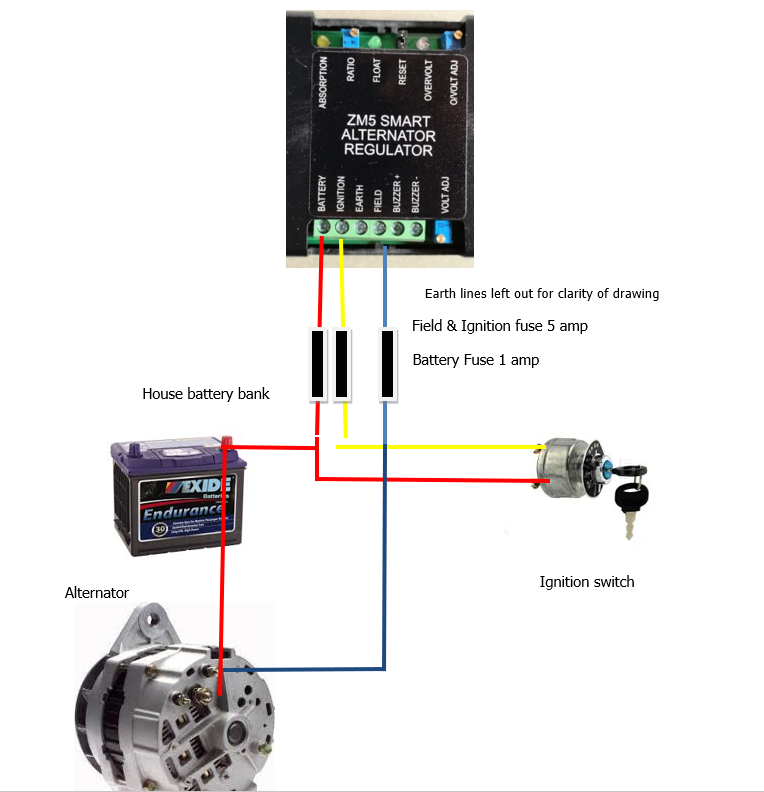
- Core Focus: Diagnostic schematic and terminal connection layout for How To Wire A Bosch Alternator.
- Target Scope: Field technicians, automotive DIYers, and residential/commercial electricians.
- Safety Rule: Always disconnect the primary power source/battery terminal and verify zero voltage with a multimeter before touching wires.
Core Concepts and Wiring Fundamentals
A Bosch alternator operates by spinning a rotor inside a stator to generate alternating current, which internal diodes rectify into direct current for the vehicle electrical grid. The main output terminal, typically labeled B+ (Battery Positive), connects directly to the positive battery post or the starter motor main lug via a heavy-gauge cable. This main charging lead must handle the full amperage output of the unit, meaning wire cross-section and terminal crimp quality are critical. In addition to the B+ stud, Bosch units feature specific excitation and sensing terminals that control internal voltage regulation.
Excitation power flows through the ignition switch to awaken the internal regulator, frequently utilizing a warning lamp circuit to provide initial field flash current. Terminal D+ (sometimes labeled 61) supplies this excitation voltage and serves as the indicator light feed, extinguishing once the alternator begins self-exciting. Some modern internal-regulator units incorporate additional sensing terminals, such as S (Stator or Sense) and DF (Dynamic Field), which monitor system voltage remotely or interface with an engine control module. For complex auxiliary charging setups or custom electrical layouts, reviewing Vehicle Wiring Diagrams provides valuable context on harness integration.
[Alternator Failure Modes] — According to technical service data from the Society of Automotive Engineers (SAE), charging system voltage drops exceeding 0.5 volts across main battery cables indicate excessive resistance caused by corrosion or inadequate terminal crimping.
Diagram Explanation and Key Components
Reading a Bosch alternator schematic requires familiarity with standard terminal symbols and international automotive wiring conventions. The B+ terminal appears as a heavy threaded stud, designated for the primary power feed protected by fusible links or high-current fuses depending on the vehicle manufacturer. The D+ terminal represents the charge indicator light circuit, which relies on a specific resistance bulb to allow initial current flow without feeding excessive back-voltage into the ignition circuit. Grounding is achieved physically through the alternator housing bolted to the engine block, though auxiliary ground straps are frequently required to prevent voltage drop.
Color codes vary significantly across regions, requiring technicians to verify physical terminal stamps rather than relying solely on wire insulation hues. In North American and Australian aftermarket conversions, the main B+ lead is traditionally red or black heavy-gauge wire, while the D+ exciter wire may be brown, blue, or yellow depending on the vehicle make. European original equipment manufacturers often utilize standardized color mapping governed by DIN 72552 standards, where blue designates alternator excitation lines. When integrating auxiliary components or custom relay triggers into the charging circuit, referencing Relay and Component Wiring Diagrams ensures proper control circuit isolation.
Common Problems and Troubleshooting Methods
Systematic fault-finding on a Bosch charging setup begins with a comprehensive visual inspection of all mechanical fasteners and electrical connections. Typical failures include loose B+ stud nuts, corroded eyelet terminals, broken exciter wires, and worn internal carbon brushes that fail to make contact with the slip rings. When a battery repeatedly discharges or the dash warning light remains illuminated with the engine running, diagnostic procedures must follow a logical sequence from the battery terminals back to the alternator housing.
Diagnostic testing involves measuring voltage drop across the positive charging cable while the engine runs with maximum electrical accessories engaged. A digital multimeter set to DC volts should reveal less than a half-volt drop between the B+ stud and the positive battery terminal. If the alternator fails to charge despite intact wiring, testing the field circuit voltage at the D+ terminal determines whether the internal regulator is receiving proper excitation power from the ignition switch. For broader electrical anomalies unrelated to direct charging output, consulting Wiring Troubleshooting guides provides additional methodologies for isolating parasitic drains and high-resistance faults.
Practical Tips and Safety Considerations
Working on automotive charging systems involves high continuous amperage capable of producing severe electrical burns and arc flashes. Always disconnect the negative battery cable before servicing alternator wiring to prevent accidental short circuits against the vehicle chassis. Select wire gauge sizes that match or exceed the maximum rated amperage output of the unit, utilizing heat-shrink tubing and marine-grade tinned copper terminals to resist under-hood corrosion. Never disconnect the battery while the engine is running to test an alternator, as this sudden load dump generates destructive voltage spikes that can instantly destroy sensitive engine control modules and radio equipment.
Mechanics in the UK and Australia must adhere to local automotive modification standards such as BS 7671 or AS/NZS codes when routing auxiliary wiring through engine bays. Ensure all wiring harnesses are secured away from moving belts, exhaust manifolds, and sharp sheet metal edges using insulated clamps and convoluted tubing. Double-check all terminal torque specifications to eliminate loose connections, which represent the primary source of intermittent charging faults and thermal degradation in high-output electrical systems.
Conclusion
Mastering how to wire a Bosch alternator ensures dependable vehicle operation and protects sensitive electrical architecture from over-voltage and short-circuit damage. Proper identification of B+, D+, and ground connections forms the foundation of any successful charging system installation or repair. Diligent attention to wire sizing, terminal cleanliness, and mechanical security prevents premature component failure under demanding operating conditions. Adhering to systematic diagnostic procedures enables technicians to isolate faults efficiently without unnecessary parts replacement. For further guidance on designing and repairing complex electrical systems, explore Wiring Diagram Basics to refine schematic interpretation skills.
Quick Wiring Specifications & Terminal Guide
| Component / Circuit | Standard Wire Gauge | Recommended Protection |
|---|---|---|
| Control & Trigger Signals | 18 – 20 AWG | 5A – 7.5A Inline Fuse |
| Standard Auxiliary Load | 14 – 16 AWG | 15A – 20A Circuit Breaker |
| Main Power Feed / Supply | 10 – 12 AWG | 30A – 40A Heavy-Duty Relay |
Images References


