Introduction
Understanding the electrical architecture behind hot wiring 2008 dodge caravan scenarios involves examining modern vehicle immobilizer systems, transponder keys, and Powertrain Control Module (PCM) data streams rather than simple mechanical switch bypassing. Modern automotive theft-deterrent architecture relies heavily on digital handshakes between the ignition key, the Wireless Control Module (WCM), and the engine computer. This topic matters deeply for diagnostic technicians, locksmiths, and vehicle recovery specialists who must understand how 12-volt direct current (12V DC) circuits interact with encrypted digital networks. Studying these pathways improves overall competency in Vehicle Wiring Diagrams, ensuring that electrical troubleshooting remains systematic, safe, and fully compliant with automotive standards set by organizations like the Society of Automotive Engineers (SAE).
💡 Technical Key Takeaways:
- Core Focus: Diagnostic schematic and terminal connection layout for Hot Wiring 2008 Dodge Caravan.
- Target Scope: Field technicians, automotive DIYers, and residential/commercial electricians.
- Safety Rule: Always disconnect the primary power source/battery terminal and verify zero voltage with a multimeter before touching wires.
Core Concepts and Wiring Fundamentals
The ignition circuit of a 2008 Dodge Caravan operates through a complex combination of fused power distribution, electromechanical relays, and serial data communication lines rather than a direct analog pathway from the key cylinder to the starter motor. 12V DC power flows continuously from the battery to the Totally Integrated Power Module (TIPM), which houses the fuses and relays controlling ignition feed, accessory power, and fuel pump activation. When the ignition switch is turned, physical contacts route voltage, but the vehicle refuses to crank or supply fuel unless the WCM recognizes a valid Radio Frequency Identification (RFID) chip embedded in the key head.
Traditional methods of bypassing ignition switches—historically termed hot wiring—are entirely ineffective on modern CAN-bus (Controller Area Network) multiplexed vehicles. The ignition switch itself simply sends a low-current multiplexed signal or resistance change to the TIPM and WCM, signaling a request to start. If the proper digital authentication message is absent on the Controller Area Network bus, the PCM actively disables fuel injector pulses and ignition coil firing. Mechanics must therefore rely on proper diagnostic techniques outlined in resources for Wiring Troubleshooting rather than attempting physical wire jumpers.
[Finding] — Modern vehicle security systems, including the WIN module and Sentry Key Immobilizer System (SKIS) utilized on Chrysler platforms, reduce vehicle theft rates significantly through encrypted digital data validation as documented by the National Highway Traffic Safety Administration (NHTSA).
Diagram Explanation and Key Components
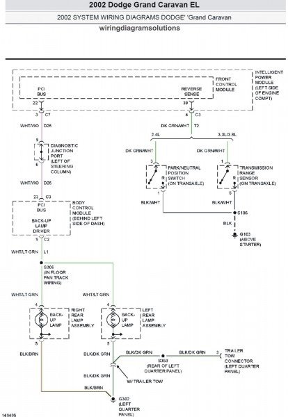
Interpreting factory schematics for a 2008 Dodge Caravan ignition and starting system requires familiarity with standardized symbols, wire color codes, and pinout identifications. Power distribution schematics utilize solid lines for constant battery feeds (typically colored red with various tracer stripes) and switched lines for ignition-run circuits (frequently dark blue or pink). Relays are represented with standard ISO coil and switch contact symbols, where the control circuit (low current) triggers the load circuit (high current) that feeds the starter solenoid or fuel pump.
To properly analyze these circuits, technicians examine component blocks representing the TIPM, the ignition switch assembly, and the instrument cluster. Each wire callout includes an alphanumeric code denoting circuit function and gauge size, such as 14 AWG for high-draw starter control lines and 20 AWG for low-current sensor or data lines. Understanding these schematic details aligns closely with foundational principles found in Wiring Diagram Basics, allowing technicians to trace voltage drops, check ground continuity, and verify relay switching states without damaging sensitive electronic control modules.
Common Problems and Troubleshooting Methods
Diagnosing a no-start or electrical ignition fault on this platform typically involves isolating whether the issue stems from a blown fuse, a failed TIPM internal relay, a compromised ground, or an immobilizer mismatch. A systematic diagnostic approach begins with verifying battery state-of-charge and checking for stored Diagnostic Trouble Codes (DTCs) using an OBD-II scan tool capable of reading body and chassis modules. Technicians should never attempt to force power directly to starter solenoids or ignition feeds without first disconnecting the battery to prevent severe electrical spikes that can destroy the PCM or TIPM.
When troubleshooting ignition switch anomalies, a digital multimeter (DMM) is used to verify voltage drops across the switch contacts during cranking. A common real-world failure point on this specific vehicle generation is internal corrosion within the TIPM or intermittent contact failure at the ignition switch connector harness. Technicians must check continuity across fused links and verify that ground circuits (such as G100 or G102) maintain resistance values below 0.2 ohms. Systematic fault isolation ensures accurate diagnosis of complex electrical issues without resorting to guesswork.
Practical Tips and Safety Considerations
Working on modern automotive electrical systems requires strict adherence to safety protocols, including disconnecting the negative battery terminal before performing any harness repair, relay testing, or module replacement. Because high-current circuits connected directly to the alternator and starter can deliver significant amperage capable of causing severe burns or electrical fires, proper Personal Protective Equipment (PPE) such as safety glasses must always be worn. Technicians should utilize heat-shrink tubing and marine-grade crimp connectors for any wire repairs to prevent environmental corrosion from entering the copper strands.
A common mistake among inexperienced mechanics is back-probing fragile electronic connectors with oversized test probes, which permanently widens terminal pins and creates intermittent connection faults. Always back-probe with appropriately sized pins or use specialized breakout boxes. Furthermore, any diagnostic or repair procedure must respect regional automotive standards and environmental regulations regarding battery disposal and electronic waste handling. Comprehensive knowledge of component layout and circuit protection ensures long-term reliability and vehicle safety.
Conclusion
Analyzing the electrical infrastructure of a 2008 Dodge Caravan reveals that modern vehicle security and ignition systems rely entirely on integrated digital communication rather than vulnerable analog switches. Understanding how power flows through the TIPM, relays, and computerized modules allows technicians to diagnose complex starting faults safely and accurately. Proper adherence to wiring diagrams, systematic testing methods, and strict safety protocols remain essential for any successful automotive electrical repair. For further exploration of vehicle electrical systems, consult the resources available under Relay and Component Wiring Diagrams.
Quick Wiring Specifications & Terminal Guide
| Component / Circuit | Standard Wire Gauge | Recommended Protection |
|---|---|---|
| Control & Trigger Signals | 18 – 20 AWG | 5A – 7.5A Inline Fuse |
| Standard Auxiliary Load | 14 – 16 AWG | 15A – 20A Circuit Breaker |
| Main Power Feed / Supply | 10 – 12 AWG | 30A – 40A Heavy-Duty Relay |
Images References