Introduction
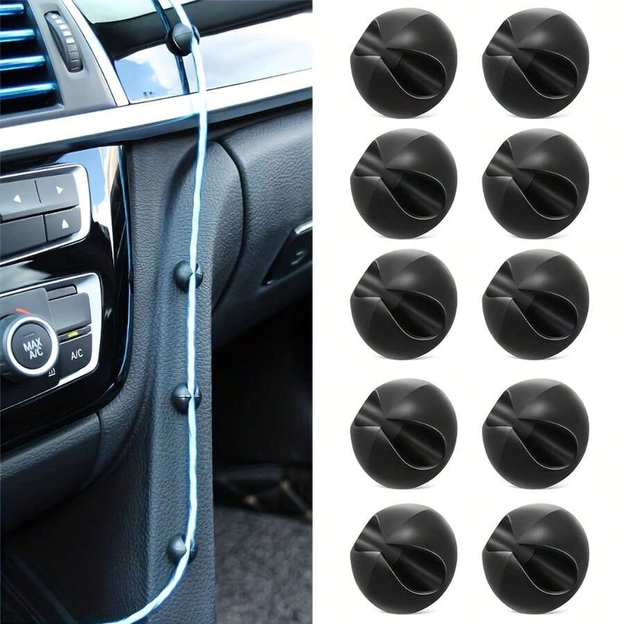
An automotive cable organizer is a dedicated mechanical management system engineered to bundle, route, and secure 12V and 24V wiring harnesses against physical abrasion, thermal degradation, and excessive vibration. According to SAE J1128 automotive wiring standards, proper electrical cable containment is mandatory to prevent insulation failure and subsequent short circuits within restricted vehicular chassis spaces. Systematic organization ensures that multi-circuit paths remain accessible for diagnostic tracing, preventing the chaotic tangles that frequently compromise complex low-voltage systems. Integrating structured loom, split tubing, or high-tensile fasteners transforms an unreliable nest of wires into a clean, serviceable schematic layout that aligns perfectly with standard Vehicle Wiring Diagrams.
Wiring Technical Snapshot:
- Core Focus: Protection and spatial arrangement of low-voltage automotive circuits.
- Target Scope: 12V/24V chassis wiring, auxiliary lighting, and engine bay harnesses.
- Key Recommendation: Secure all bundled runs away from sharp sheet metal edges and moving steering components.
Core Principles and Detailed Overview
Effective cable management requires a thorough understanding of mechanical stress points, thermal boundaries, and current-carrying capacities across diverse harness runs. An automotive cable organizer physically isolates sensitive sensor signals from high-current power feeds, mitigating electromagnetic interference (EMI) that can corrupt delicate electronic control unit (ECU) data streams. When establishing structured layouts inside the engine compartment or beneath the dash, technicians rely heavily on accurate Wiring Diagram Basics to map out branch circuits before applying permanent sleeving or anchors. Utilizing flame-retardant polyethylene or braided nylon expandable sleeving guarantees that individual conductors maintain structural integrity under continuous exposure to engine heat cycles, road salt, and petrochemical fluids.
Key Specifications and Breakdown
| Circuit / Terminal | Standard Wire Color / Gauge | Operational Role & Safety Check |
|---|---|---|
| Battery Feed / Main Power | Red / 8 AWG – 4 AWG | Delivers unswitched high current; verify continuous insulation and secure anchoring. |
| Ignition Switched Power | Yellow or Orange / 14 AWG – 12 AWG | Powers accessory relays; check voltage drop with a digital multimeter under load. |
| Chassis Ground Return | Black / 16 AWG – 10 AWG | Completes low-voltage return path; inspect for low resistance and corrosion-free mating. |
Electrical conductors and wiring harnesses must be securely fastened and protected against physical damage, friction, and extreme thermal conditions to prevent arc faults and catastrophic system failures. — National Fire Protection Association (NFPA)
Step-by-Step Practical Application and Guidelines
Implementing an organized harness system begins with disconnecting the battery negative terminal to eliminate accidental short circuits during physical routing. Technicians must first lay out the entire wiring run alongside the corresponding Relay and Component Wiring Diagrams to verify correct circuit lengths and terminal placements. Once the path is mapped, group related low-voltage conductors into split-loom tubing or braided sleeving, leaving slight slack near engine vibration points to prevent terminal tension. Secure the organizer assembly to factory mounting studs or welded chassis tabs using UV-resistant nylon zip ties or rubber-coated P-clamps, ensuring zero contact with exhaust manifolds, steering shafts, or sharp body panels.
Common Challenges and How to Avoid Them
Over-tightening zip ties represents the most frequent cause of internal conductor breakage and insulation piercing within bundled automotive harnesses. Technicians must utilize flush-cutters and avoid crushing inner wire strands, which can restrict current flow and create hidden high-resistance hot spots. Furthermore, bundling sensitive communication lines directly alongside heavy-duty inductive loads—such as starter solenoids or cooling fan motors—invites erratic sensor behavior that complicates systematic Wiring Troubleshooting. Maintaining physical separation, utilizing shielded shielding braids, and carefully routing power feeds away from signal circuits will ensure long-term electrical reliability.
💬 Frequently Asked Questions
Explore More Wiring Diagrams and Schematics on ReadWires
Mastering automotive electrical systems demands access to accurate schematics, comprehensive terminal breakdowns, and proven troubleshooting methodologies. Whether updating complex auxiliary accessories or tracing factory faults, professional reference materials streamline every diagnostic step. Browse the complete collection of professional automotive schematics and technical reference guides available right now on ReadWires.com to elevate your electrical repair capabilities.
Visual Reference Gallery