Introduction
An alexa light dimmer switch uk is a smart home lighting control device designed for UK electrical standards (230V AC, 50Hz) that integrates voice automation with phase-cut dimming capabilities. According to IEEE Electrical Safety Standards, proper verification of circuit isolation and terminal torque ratings is mandatory before installing any mains-connected smart wiring infrastructure. Integrating these smart switches into residential Home Electrical Wiring Diagrams requires strict adherence to British Standard BS 7671 for electrical installations. Mastering the installation of voice-activated controls demands a precise understanding of neutral wire availability, load wattage calculations, and systematic diagnostic procedures using a digital multimeter.
Wiring Technical Snapshot:
- Core Focus: Installation, neutral requirements, and diagnostic troubleshooting of UK smart lighting dimmers.
- Target Scope: 230V residential AC mains circuits and retrofit voice-control module integrations.
- Key Recommendation: Always verify circuit dead status using a calibrated voltage tester before touching internal conductors.
Core Principles and Detailed Overview
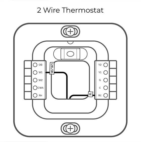
An alexa light dimmer switch uk operates by modulating the AC sine wave through trailing-edge or leading-edge semiconductor components to regulate luminaire intensity via smart assistant commands. Trailing-edge dimmers are typically required for modern LED fixtures to prevent flicker and audible buzzing. Technicians reviewing Appliance and Device Wiring must identify whether the installation site features a dedicated neutral conductor in the back box. Many legacy UK properties utilize loop-in wiring topologies where only live and switched-live conductors are present at the switch drop, necessitating either a no-neutral smart dimmer or the installation of a bypass capacitor across the lighting load.
Key Specifications and Breakdown
| Circuit / Terminal | Standard Wire Color / Gauge | Operational Role & Safety Check |
|---|---|---|
| Live (L1 / Common) | Brown (1.0mm² to 1.5mm²) | Carries incoming 230V AC line voltage; verify zero potential with a multimeter. |
| Switched Live (L2 / Out) | Brown or Sleeved Black (1.0mm²) | Delivers modulated voltage to the luminaire; check continuity to the lamp holder. |
| Neutral (N) | Blue (1.0mm² to 1.5mm²) | Completes the low-voltage control circuit; required for Wi-Fi/Zigbee transceivers. |
Electrical installations must comply with strict national safety codes to prevent arc faults, thermal overload, and component degradation — Electrical Safety Foundation International (ESFI)
Step-by-Step Practical Application and Guidelines
Installing an alexa light dimmer switch uk begins with isolating the circuit at the consumer unit and proving dead using a GS38-compliant voltage indicator. Remove the existing faceplate and map out the existing wiring configuration against standard Wiring Diagram Basics to prevent terminal misplacement. Connect the incoming live feed to the common terminal, the switched live to the load terminal, and the neutral conductor to the neutral port if the smart switch model requires a complete circuit. Secure all terminal screws to the manufacturer’s specified torque rating to eliminate high-resistance joints that generate hazardous thermal hotspots. Restore mains power only after verifying that all exposed copper conductors are fully enclosed within the insulated back box.
Common Challenges and How to Avoid Them
LED micro-flicker and relay chatter are the most frequent issues encountered when retrofitting smart dimmers into older UK lighting circuits. These anomalies typically stem from incompatible minimum load thresholds or the complete absence of a neutral conductor in standard 2-wire switch configurations. Technicians should consult advanced Wiring Troubleshooting guides to isolate ground-loop feedback and verify signal impedance values. Installing a load compensation adapter parallel to the primary light fixture frequently resolves residual glow and erratic dimming behavior across low-wattage LED arrays.
💬 Frequently Asked Questions
Explore More Wiring Diagrams and Schematics on ReadWires
Accurate documentation is the foundation of every successful electrical installation, automotive modification, and smart home upgrade. Professionals and hobbyists can explore comprehensive schematics, reference guides, and layout collections directly across ReadWires.com to ensure total safety and compliance on every project.
Visual Reference Gallery