Introduction
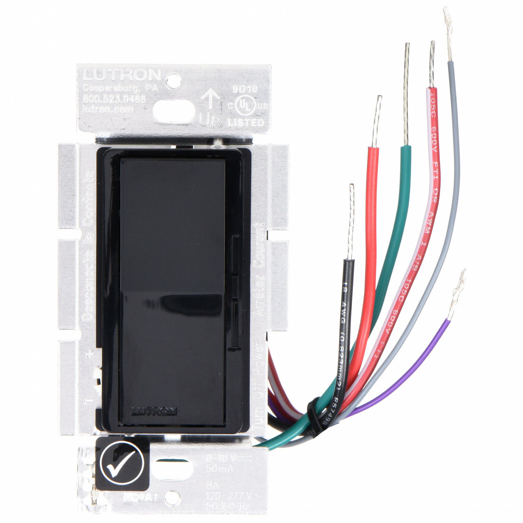
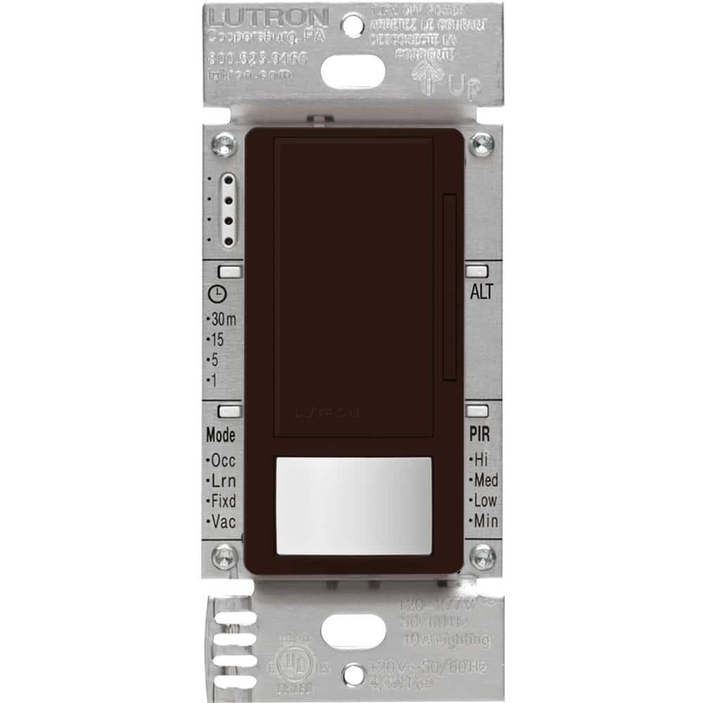
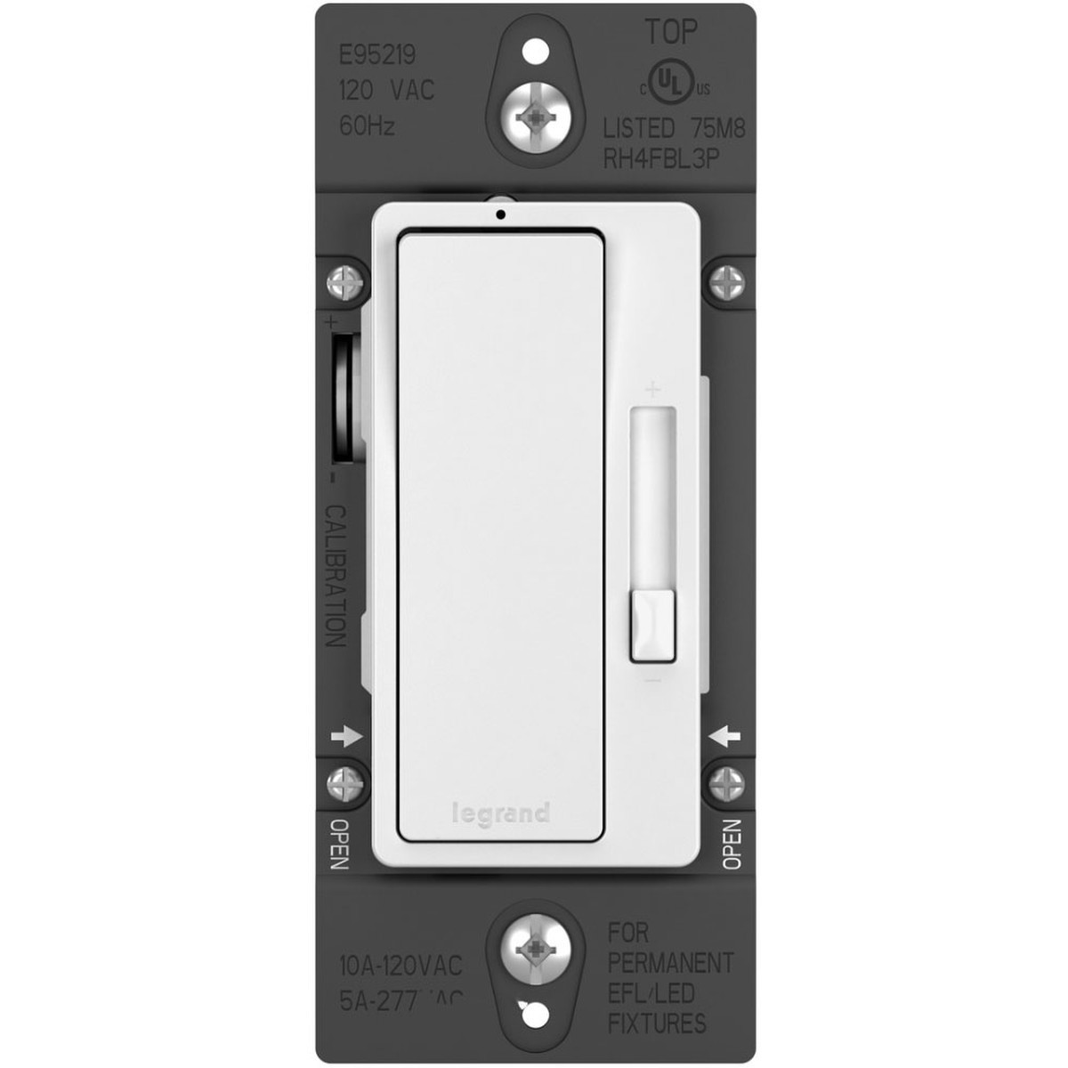
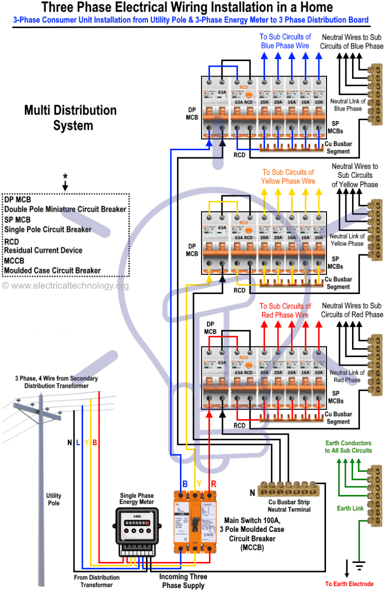
A 277 volt light dimmer switch is a specialized commercial-grade electrical control device engineered to regulate lighting output across high-voltage single-phase or phase-to-neutral commercial distribution circuits without experiencing thermal overload or component breakdown. According to the National Electrical Code (NFPA 70 / NEC), commercial lighting systems operating at 277V require listed and rated switching hardware specifically designed to handle higher voltage stress compared to standard residential 120V setups. Mastering the installation, integration, and diagnostics of these high-voltage devices is critical for electricians, facility maintenance technicians, and advanced DIY builders working within commercial or industrial real estate. Proper familiarity with Home Electrical Wiring Diagrams and structured installation guidelines ensures that high-voltage circuits remain safe, compliant, and fully operational under continuous load demands.
Wiring Technical Snapshot:
- Core Focus: High-voltage commercial lighting control and phase-cut dimming mitigation for 277V distribution lines.
- Target Scope: Commercial facility maintenance, advanced electrical installations, and strict adherence to strict electrical safety protocols.
- Key Recommendation: Always verify circuit de-energization with a calibrated digital multimeter before touching any physical terminals or conductors.
Core Principles and Detailed Overview
A 277 volt light dimmer switch operates by interrupting or modulating the AC sine wave through specialized semiconductor components, primarily triacs or insulated-gate bipolar transistors (IGBTs), tailored for high-voltage industrial applications. Unlike standard 120V household dimmers that fail catastrophically when subjected to 277 volts from a 480Y/277V three-phase wye system, 277V rated devices utilize heavy-duty internal heat sinks and robust voltage barriers to dissipate thermal energy effectively. Understanding Appliance and Device Wiring principles helps technicians evaluate ballast compatibility, driver loads, and neutral conductor placement. Technicians must differentiate between traditional incandescent/halogen dimming and modern 0-10V dimming architecture, where the 277V line feeds the ballast power while separate low-voltage signal wires manage the dimming curve.
Key Specifications and Breakdown
| Circuit / Terminal | Standard Wire Color / Gauge | Operational Role & Safety Check |
|---|---|---|
| Hot Input (Line) | Brown or Black (10–12 AWG) | Carries incoming 277V potential; verify zero energy with a category-rated DMM. |
| Hot Output (Load) | Red or Striped Conductor (12 AWG) | Delivers controlled voltage to the light fixture; check for continuity when closed. |
| Equipment Ground | Bare Copper or Green (12 AWG) | Provides fault protection path; measure resistance to earth ground (< 1 ohm). |
Electrical installations involving commercial-grade 277V circuits must strictly enforce lockout/tagout (LOTO) protocols to prevent catastrophic arc flash incidents and severe electrical shock. — National Fire Protection Association (NFPA)
Step-by-Step Practical Application and Guidelines
Installing and troubleshooting a 277 volt light dimmer switch requires methodical planning, precise physical connections, and stringent verification steps to prevent component failure or personal injury. Begin by executing a complete lockout/tagout at the breaker panel, then verify zero voltage at the switch box using a multimeter verified on a known live source. Strip the conductors to the exact strip-length specified by the dimmer manufacturer, ensuring no bare copper is exposed outside the terminal block. Secure all wire nuts or screw terminals tightly to prevent high-resistance connections that generate excessive heat under high-voltage loads. Consult Wiring Troubleshooting guides when tracing intermittent flickering, buzzing ballasts, or unexpected thermal trips in complex commercial runs.
Common Challenges and How to Avoid Them
Incompatible LED drivers and mismatched ballast loads represent the most frequent operational hurdles encountered when deploying a 277 volt light dimmer switch in modern retrofits. Technicians frequently encounter audible buzzing or strobing lights caused by pairing forward-phase dimmers with electronic drivers requiring reverse-phase control or dedicated 0-10V sinking signals. Another critical issue involves thermal overload inside shallow junction boxes, which restricts proper heat dissipation for heavy-duty 277V dimming units. Always confirm that the total wattage of the connected fixtures does not exceed eighty percent of the dimmer switch’s maximum rated capacity, and verify that all neutral wires are properly mapped to prevent floating neutral hazards across multi-phase installations.
💬 Frequently Asked Questions
Explore More Wiring Diagrams and Schematics on ReadWires
Expanding technical expertise across industrial, commercial, and automotive electrical architectures requires access to verified, high-quality documentation. Professionals and hobbyists can continue exploring comprehensive schematics, diagnostic procedures, and installation guides by visiting ReadWires.com to ensure every project meets rigorous safety and performance standards.
Visual Reference Gallery