Introduction
Auto wire wrap refers to specialized protective wrapping materials, spiral tubing, or self-fusing tape applied to automotive wiring harnesses to safeguard low-voltage circuits against abrasion, high engine bay temperatures, and fluid contamination. According to SAE J1128 automotive wiring standards, secondary wire protection must maintain physical integrity and insulation properties under severe environmental stressors, including vibration and chemical exposure. Modern 12V and 24V electrical architectures in contemporary vehicles require robust bundling techniques to prevent harness chafing and subsequent short circuits. Technicians rely on clear Vehicle Wiring Diagrams to trace bundled circuits during complex diagnostic procedures. Proper application of wire wrapping materials ensures that power distribution, sensor networks, and communication lines remain mechanically secure and electrically isolated throughout the operational lifespan of the machinery.
Wiring Technical Snapshot:
- Core Focus: Mechanical protection, thermal insulation, and structured organization of automotive wiring harnesses.
- Target Scope: 12V/24V automotive systems, aftermarket electronics, and industrial mobile equipment.
- Key Recommendation: Select temperature-rated split loom or braided sleeving matching the specific thermal zone of the engine compartment.
Core Principles and Detailed Overview
Auto wire wrap principles dictate that every protective layer must match the thermal index and mechanical demands of the specific installation zone. Direct diagnostic evaluation begins with understanding how harness routing interacts with moving mechanical parts and high-heat exhaust components. When reviewing Wiring Diagram Basics, technicians must account for physical harness thickness introduced by multi-layer protective wraps to prevent routing pinches during reassembly. High-density polyethylene split loom provides standard abrasion defense for interior dashes, whereas high-temperature fiberglass or silicone-coated wraps are mandatory within direct engine bays. Systematic Wiring Troubleshooting requires careful unzipping or unwrapping of damaged harness sections to inspect inner copper strands for thermal oxidation, corrosion, or insulation breakdown caused by friction or chemical fluid ingress.
Key Specifications and Breakdown
| Circuit / Terminal | Standard Wire Color / Gauge | Operational Role & Safety Check |
|---|---|---|
| Battery Power Feed | Red / 8 AWG to 20 AWG | Delivers unswitched DC power; verify inline fuse integrity with a digital multimeter. |
| Chassis Ground | Black / 10 AWG to 18 AWG | Completes current return path; measure voltage drop to ensure clean earth continuity. |
| Sensor Signal Line | Variable / 18 AWG to 22 AWG | Transmits low-voltage analog data; inspect shielded wraps for ground loop interference. |
Electrical conductors and protective sheathing must be rated to withstand maximum continuous operating temperatures and localized thermal radiation loads encountered during heavy-duty operational cycles. — National Fire Protection Association (NFPA)
Step-by-Step Practical Application and Guidelines
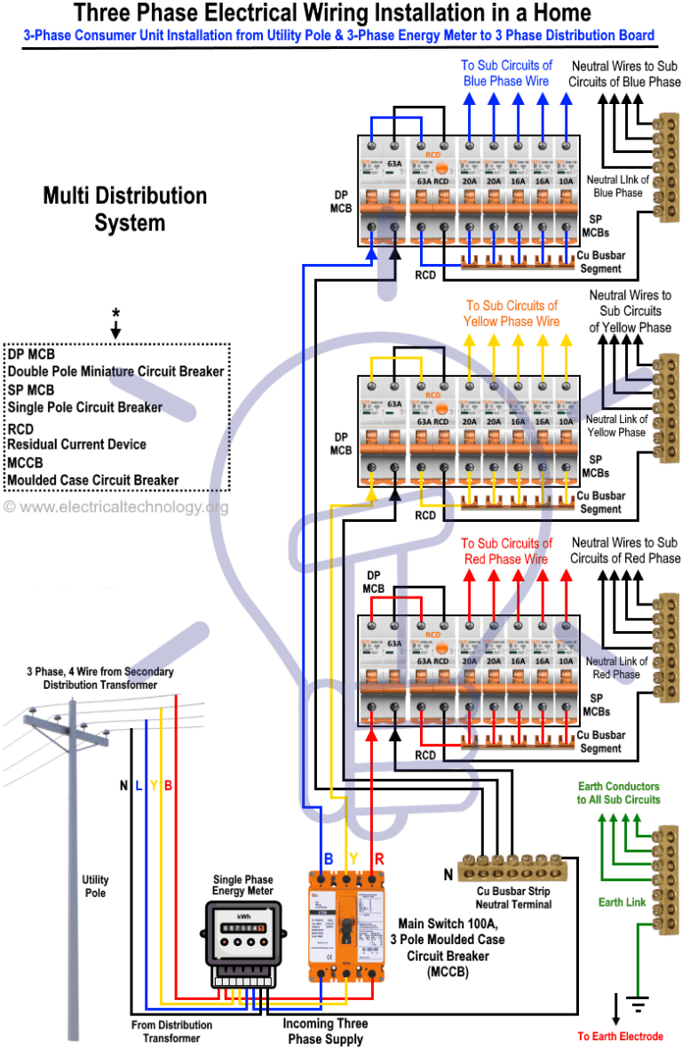
Auto wire wrap application requires thorough circuit de-energization, precise harness cleaning, and disciplined mechanical retention to eliminate future failure points. Technicians must first disconnect the battery negative terminal before cutting zip ties or peeling back legacy electrical tape. Inspecting underlying circuits against schematic references found in Home Electrical Wiring Diagrams or automotive equivalents ensures no crossed paths exist prior to re-bundling. Clean the bare wire bundle using an electrical contact cleaner to remove oil residues, then apply spiral wrap or expandable braided sleeving while maintaining moderate tension. Secure the terminal ends of the wrap with high-grade self-fusing silicone tape or UV-resistant cable ties to prevent shifting. Finally, anchor the wrapped harness securely to vehicle body tabs to eliminate vibration fatigue.
Common Challenges and How to Avoid Them
Auto wire wrap failures typically stem from incorrect material selection, improper thermal zoning, and excessive mechanical tension applied during harness installation. Over-tightening cable ties over soft split-loom tubing can deform inner wire insulation, leading to internal conductor shorting over time. Technicians must also avoid placing standard polyethylene wraps near exhaust headers or turbochargers where radiant heat exceeds material thresholds. Utilizing incorrect gauge sizes or failing to check circuit continuity after re-wrapping can trap intermittent faults inside the newly sealed harness. Maintaining neat routing geometry prevents trapped moisture pockets and ensures that diagnostic access points remain accessible for future multimeter testing.
💬 Frequently Asked Questions
Explore More Wiring Diagrams and Schematics on ReadWires
Mastering vehicle electrical systems requires continuous access to reliable schematics, proper harness protection techniques, and precise diagnostic methods. Professionals and enthusiasts can expand their technical expertise by exploring comprehensive reference materials and structured schematics available across the complete library at ReadWires.com, ensuring every circuit remains safe, organized, and fully operational.
Visual Reference Gallery