Introduction
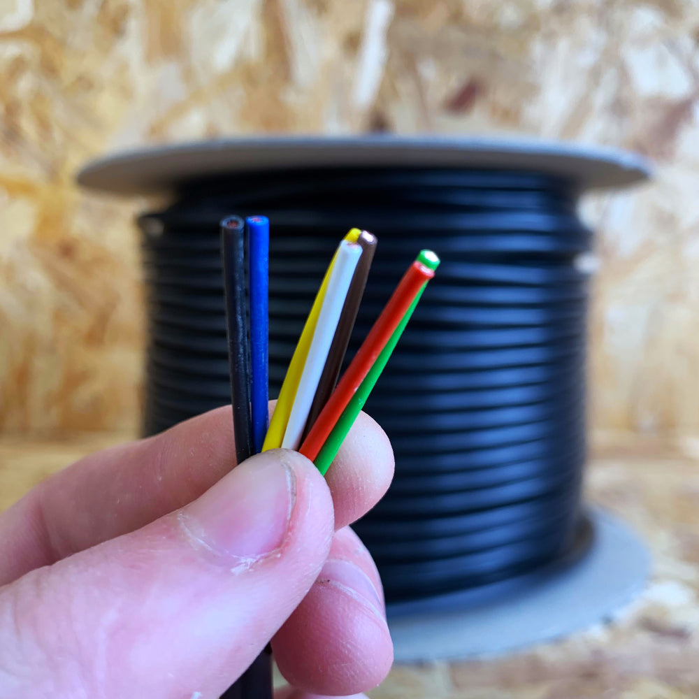
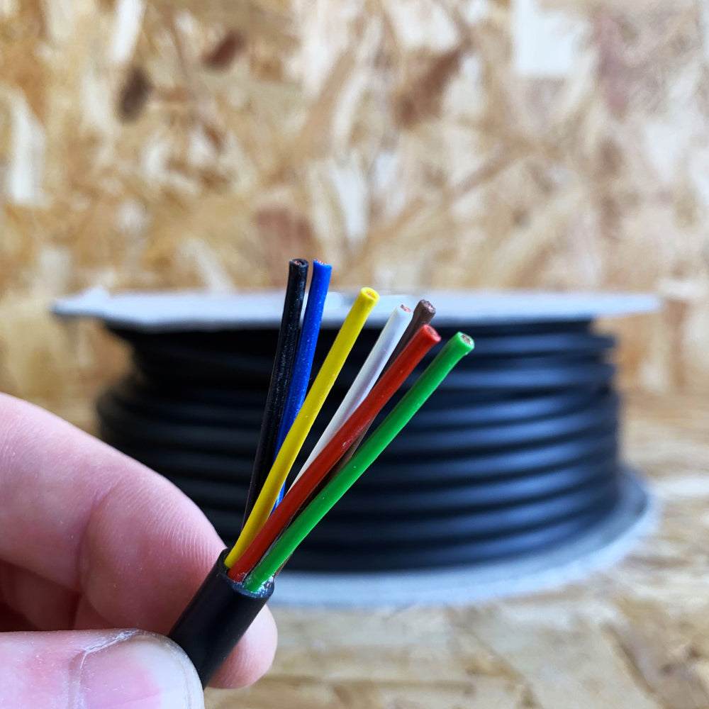
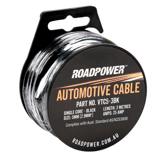
Automotive cable uk refers to standardized low-tension, high-performance copper wiring specifically manufactured to British and European standards for 12V and 24V automotive and mobile electrical systems. According to the Society of Automotive Engineers (SAE J1128) and British Standard BS 6862, automotive wiring must utilize high-conductivity annealed copper strands enclosed in robust insulation resistant to engine bay heat, oils, and battery acids. Mastering the selection, routing, and testing of these cables is essential for maintaining safe mobile electrical systems, whether diagnosing a custom harness or integrating complex Vehicle Wiring Diagrams into a vintage restoration.
Wiring Technical Snapshot:
- Core Focus: Selecting and troubleshooting standardized automotive cable uk for 12V/24V mobile circuits.
- Target Scope: Practical installation, voltage drop management, and systematic multimeter diagnosis.
- Key Recommendation: Always calculate current draw and allowable amperage limits before sizing any mobile circuit.
Core Principles and Detailed Overview
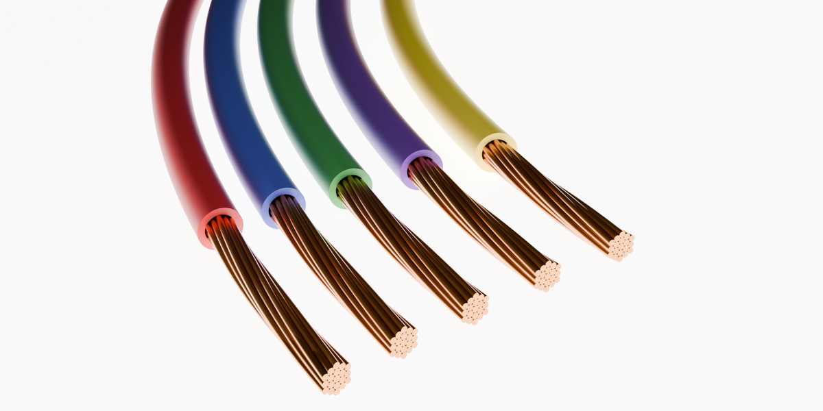
Understanding automotive cable uk requires a thorough grasp of conductor cross-sectional area (CSA), ampacity ratings, and voltage drop limits across extended vehicle chassis runs. Low-voltage DC circuits on modern vehicles experience significant resistance penalties if incorrect conductor gauges are installed, leading to component failure or thermal overload. Technicians must evaluate individual circuits by referencing comprehensive Wiring Diagram Basics to map power distribution accurately. Because automotive environments subject cables to continuous vibration, moisture ingress, and thermal cycling, standard household electrical wires are fundamentally unsafe for vehicle installation; only flexible, multi-strand copper cables compliant with UK automotive specifications should ever be deployed in mobile applications.
Key Specifications and Breakdown
| Circuit / Terminal | Standard Wire Color / Gauge | Operational Role & Safety Check |
|---|---|---|
| Battery Feed (Main Positive) | Brown / Red (10mm² to 25mm²) | Carries high current directly from alternator/battery; verify continuity with a calibrated digital multimeter. |
| Switched Ignition Power | Green / Yellow (1.5mm² to 2.5mm²) | Energizes accessory relays and ignition modules; inspect for high resistance caused by corroded terminals. |
| Chassis Earth Return | Black (2.5mm² to 6.0mm²) | Completes the negative return path to the battery; ensure low resistance (< 0.1 ohms) at clean grounding points. |
Electrical circuits must be protected by appropriately rated fuses sized to prevent conductor overheating under maximum continuous load conditions. — National Fire Protection Association (NFPA)
Step-by-Step Practical Application and Guidelines
Executing a reliable installation of automotive cable uk involves precise stripping, crimping, sealing, and secure mechanical routing along the vehicle chassis. Technicians begin by mapping the circuit topology using verified schematics, ensuring that wire lengths are kept as short as possible to minimize total voltage drop. When joining conductors, open-barrel or closed-barrel copper terminals must be attached using a professional ratchet crimper, never simple pliers, to guarantee optimal gas-tight electrical contact. Following the physical installation, every branch should be validated by checking the Wiring Troubleshooting protocols, utilizing voltage drop testing under load to confirm that resistance remains well within acceptable parameters before wrapping the harness in abrasion-resistant split-conduit or adhesive-lined heat shrink tubing.
Common Challenges and How to Avoid Them
Voltage drop, corrosion, and incorrect wire gauge selection remain the most frequent failures encountered when working with automotive cable uk in complex vehicle electrical systems. Technicians frequently overlook the accumulation of green copper corrosion underneath seemingly intact insulation, which dramatically increases circuit resistance and starves sensitive modules of required operating voltage. Undersizing replacement wires for high-current accessories such as fuel pumps or lighting upgrades will cause thermal breakdown of the insulation sheath. Diligent diagnostic testing with a digital multimeter under active load conditions prevents these persistent faults, ensuring absolute reliability across both mobile setups and auxiliary Home Electrical Wiring Diagrams adapted for vehicle power inverters.
💬 Frequently Asked Questions
Explore More Wiring Diagrams and Schematics on ReadWires
Accessing accurate, high-quality technical documentation is the cornerstone of safe and effective automotive electrical diagnostics. Explore the comprehensive resource libraries available at ReadWires.com to discover detailed schematics spanning mobile electronics, industrial setups, and specialized applications, empowering precise troubleshooting and flawless execution on every project.
Visual Reference Gallery