Introduction
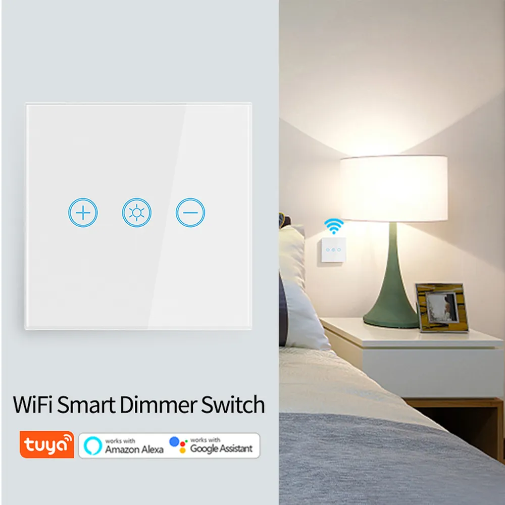
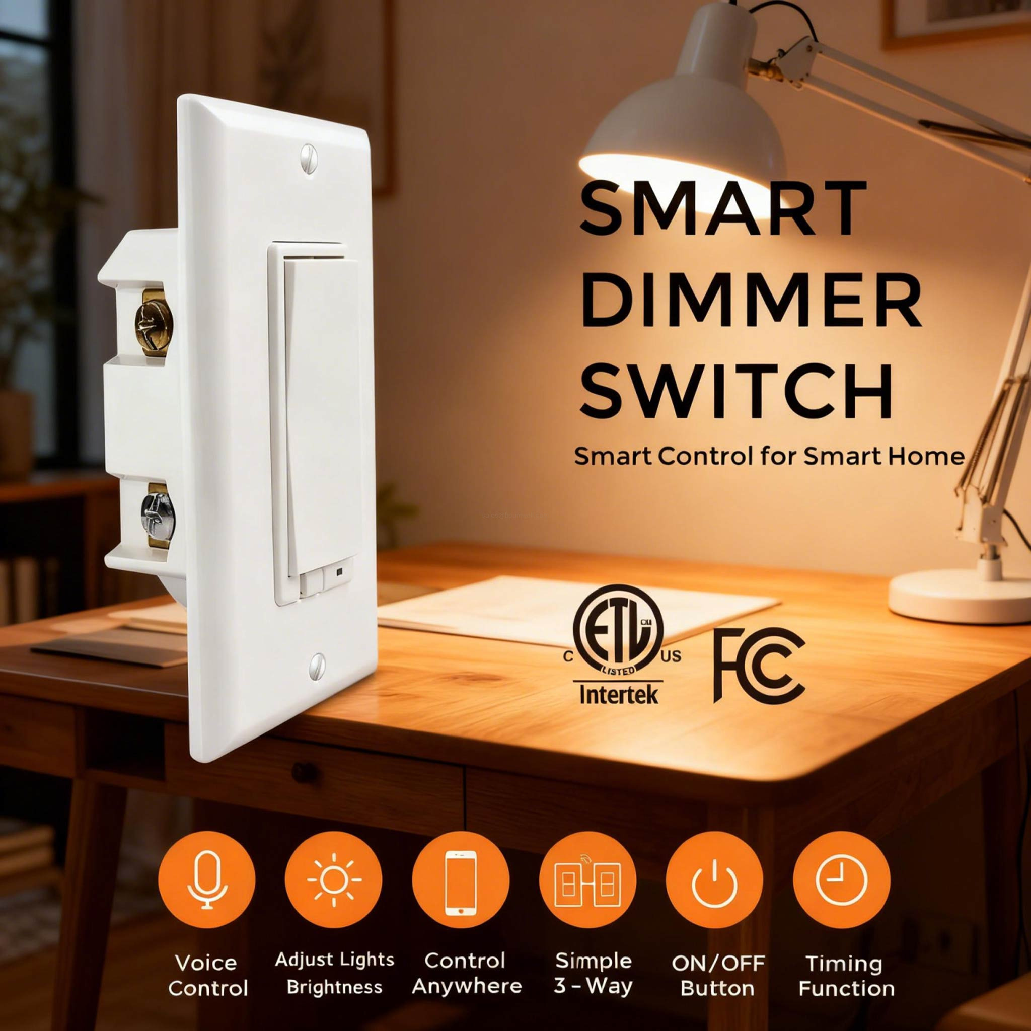
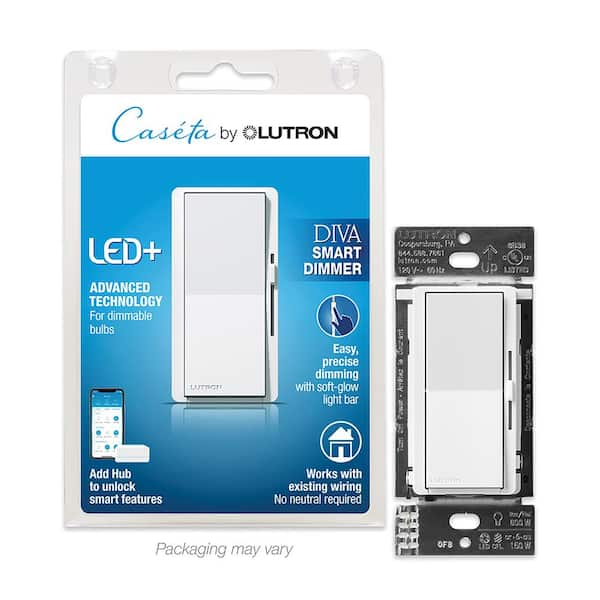
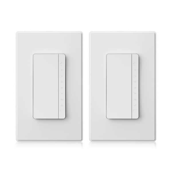
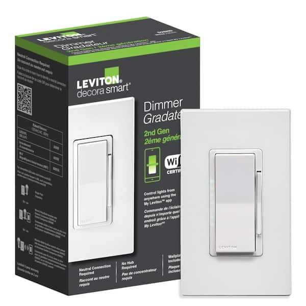
An alexa enabled light switch dimmer is a smart home automation device that replaces standard electromechanical switches to regulate fixture voltage output via voice commands or wireless automation protocols. According to the National Electrical Code (NFPA 70 / NEC), all retrofitted smart lighting control hardware must strictly comply with established enclosure rating standards, load capacity limits, and proper grounding protocols to prevent overcurrent events. Integrating these intelligent solid-state dimmers into residential structures requires a precise understanding of high-voltage alternating current circuits, phase-cut dimming topologies, and zero-wire neutral configurations. Technicians handling these installations must evaluate the physical properties of existing wall boxes, verifying spatial clearance and thermal dissipation before terminal attachment. Thorough documentation across Home Electrical Wiring Diagrams ensures that line, load, neutral, and ground conductors map accurately without creating hazardous grounding loops. Mastering the underlying circuit architecture prevents operational faults, flickering LEDs, and premature relay burnout in modern residential environments.
Wiring Technical Snapshot:
- Core Focus: Solid-state triac or MOSFET voltage regulation paired with embedded Wi-Fi or Zigbee wireless transceivers.
- Target Scope: Residential 120V/240V AC lighting distribution systems requiring smart voice-activated dimming control.
- Key Recommendation: Always verify physical neutral wire availability inside the electrical box before purchasing zero-neutral or neutral-required dimmer models.
Core Principles and Detailed Overview
Smart dimmers control illumination levels by modulating the AC sine wave through rapid solid-state switching rather than dissipating excessive energy as heat. Leading-edge and trailing-edge phase-cut methods govern how the semiconductor device chops the waveform to dim incandescent, halogen, and dimmable LED retrofit lamps. Troubleshooting these networks requires familiarity with standard residential electrical schematics found within Wiring Diagram Basics to trace continuity and voltage drop accurately. When dealing with complex multi-way setups, technicians must distinguish between standard traveler wires and dedicated smart companion switches to maintain proper bidirectional communication. Furthermore, checking operational parameters through systematic troubleshooting methods prevents phantom voltage readings and ensures stable wireless handshake execution with local routers and cloud servers.
Key Specifications and Breakdown
| Circuit / Terminal | Standard Wire Color / Gauge | Operational Role & Safety Check |
|---|---|---|
| Line (Hot Input) | Black / 14 AWG or 12 AWG | Delivers continuous 120V AC supply voltage; verify with a multimeter before handling. |
| Load (Switched Output) | Red or Black / 14 AWG or 12 AWG | Carries regulated variable voltage to the lighting fixture; check for short circuits to ground. |
| Neutral (Return Path) | White / 14 AWG or 12 AWG | Completes the low-voltage internal power circuit for the Wi-Fi module; required for many models unless specified as no-neutral. |
Electrical safety standards mandate that all metallic device yokes and ground terminals must maintain a continuous, low-impedance path back to the main service panel to facilitate rapid circuit breaker tripping during a fault condition. — Electrical Safety Foundation International (ESFI)
Step-by-Step Practical Application and Guidelines
Executing a safe and reliable installation begins with isolating the circuit at the main breaker panel and verifying zero potential using a calibrated digital multimeter. After removing the wall plate and extracting the legacy mechanical switch, identify the incoming line conductor, outgoing load wire, grounding conductor, and the bundle of neutral wires safely tucked in the back of the junction box. Connect the smart dimmer leads securely using listed wire connectors, ensuring no bare copper is exposed outside the terminal housing. Grounding the green wire of the smart switch directly to the bare copper ground bundle is non-negotiable for electrostatic discharge protection and user safety. Once physical wiring is verified against manufacturer schematics, restore power, initiate the device pairing sequence via the companion mobile application, and link the hardware to the cloud ecosystem for voice activation.
Common Challenges and How to Avoid Them
Flickering lights, unresponsiveness, and erratic relay clicking are primary symptoms of improper load compatibility or missing neutral wire pathways. Many dimmable LED bulbs require a minimum electrical load threshold to function properly without glowing dimly while switched off; installing a bypass capacitor across the fixture terminals often resolves low-wattage leakage issues. When diagnosing intermittent wireless dropouts, reference established workflows in Wiring Troubleshooting to isolate whether the fault stems from local AC line noise, weak 2.4 GHz RF signals, or physical terminal degradation. Additionally, crowding oversized smart switches into shallow retrofit junction boxes can pinch insulation and cause thermal overload, violating National Electrical Code fill capacity regulations.
💬 Frequently Asked Questions
Explore More Wiring Diagrams and Schematics on ReadWires
Mastering complex domestic and commercial electrical hardware installations requires continuous reference to verified technical documentation and professional schematics. Exploring comprehensive schematic libraries at ReadWires.com provides automotive technicians, electricians, and DIY hobbyists with the precise data required for safe, compliant, and efficient electrical system integration.
Visual Reference Gallery