Introduction
A 12 volt light switch dimmer regulates DC electrical power sent to low-voltage illumination fixtures by modulating duty cycles or restricting voltage drop, thereby controlling perceived lamp brightness in mobile, marine, and off-grid auxiliary setups. According to SAE J1128 automotive wiring standards, low-voltage direct current circuits demand precise conductor sizing and voltage drop management to prevent excessive thermal buildup across variable resistive components. Implementing a proper low-voltage modulation controller requires strict adherence to DC polarity, current capacity limits, and thermal ratings. Understanding these electrical parameters ensures safe integration into custom Vehicle Wiring Diagrams without risking circuit overloads or premature switch failure.
Wiring Technical Snapshot:
- Core Focus: Pulse width modulation (PWM) and linear voltage control for 12V and 24V DC illumination circuits.
- Target Scope: Automotive interiors, marine cabins, RV conversions, and specialized low-voltage DC auxiliary spaces.
- Key Recommendation: Match controller amperage ratings to total continuous load draw while maintaining a mandatory 20% safety margin.
Core Principles and Detailed Overview
Pulse width modulation represents the primary electronic method utilized by a 12 volt light switch dimmer to regulate illumination output efficiently across LED and incandescent loads. Direct current dimmers operate by rapidly switching the ground or positive path on and off at high frequencies, varying the duty cycle from zero to one hundred percent without dissipating excessive heat into the dashboard or housing structure. Standard rheostats designed for 120V AC residential grids must never be substituted into 12V DC systems, as low-voltage direct current requires specialized solid-state MOSFET switching architecture to handle high amperage without thermal failure. Technicians designing custom setups should consult Wiring Diagram Basics to correctly map out positive feeds, switched legs, and dedicated ground paths before terminating physical connections.
Key Specifications and Breakdown
| Circuit / Terminal | Standard Wire Color / Gauge | Operational Role & Safety Check |
|---|---|---|
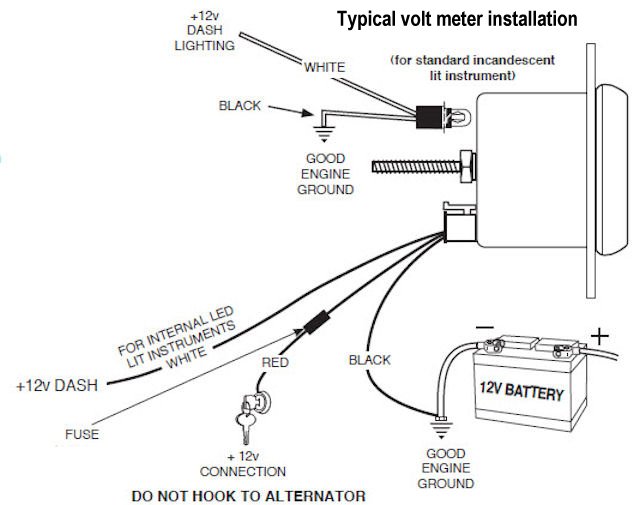
| Power Input (12V+) | Red / Brown (14 AWG to 12 AWG) | Delivers fused positive DC voltage from the power distribution block; verify continuity and voltage with a digital multimeter. |
| Switched Output (Dimmer) | Blue / Yellow (16 AWG to 14 AWG) | Transfers modulated DC power directly to the lighting load; measure duty cycle and voltage drop under full illumination load. |
| Ground Return (Common) | Black (16 AWG to 12 AWG) | Completes the electrical circuit back to chassis ground or battery negative; inspect for low resistance and secure bare-metal contact. |
Electrical circuits operating at 12 volts DC require careful conductor sizing and overcurrent protection to mitigate elevated amperage demands and prevent localized resistive heating. — National Fire Protection Association (NFPA)
Step-by-Step Practical Application and Guidelines
Installing a 12 volt light switch dimmer requires systematic disconnection of the primary battery power source to prevent accidental short circuits during wire stripping and terminal crimping. Begin by identifying the supply conductor, measuring open-circuit voltage with a calibrated digital multimeter, and verifying that the inline fuse rating matches the maximum current draw of the intended lighting array. Mount the dimmer module in an area with adequate ambient ventilation, particularly when driving high-wattage LED strips or legacy halogen fixtures that generate substantial thermal energy. Secure all crimp terminals using proper ratcheting tools, apply heat-shrink tubing to seal against moisture and vibration, and test system operation meticulously before resecuring interior trim panels or enclosures.
Common Challenges and How to Avoid Them
High-frequency audible buzzing and LED flickering represent the most frequent complications encountered during the integration of a 12 volt light switch dimmer into sensitive automotive or marine electrical architectures. Audible whine usually stems from low-frequency pulse width modulation interfering with audio channels or improper grounding, which can be mitigated by installing an independent chassis ground or a dedicated DC-to-DC noise filter. Furthermore, connecting non-dimmable LED fixtures to a trailing-edge or cheap resistive dimmer frequently results in rapid diode degradation or sudden lamp failure. Technicians troubleshooting complex electrical faults can reference Wiring Troubleshooting methodologies to isolate voltage drops, verify switch duty cycles, and restore proper circuit functionality.
💬 Frequently Asked Questions
Explore More Wiring Diagrams and Schematics on ReadWires
Mastering low-voltage illumination control and custom circuit modifications requires access to precise technical documentation, standardized schematics, and expert diagnostic guides. Professionals and DIY builders can expand their electrical knowledge by browsing comprehensive archives available through ReadWires.com to ensure safe, efficient, and reliable wiring installations across all automotive and residential projects.
Visual Reference Gallery