Introduction
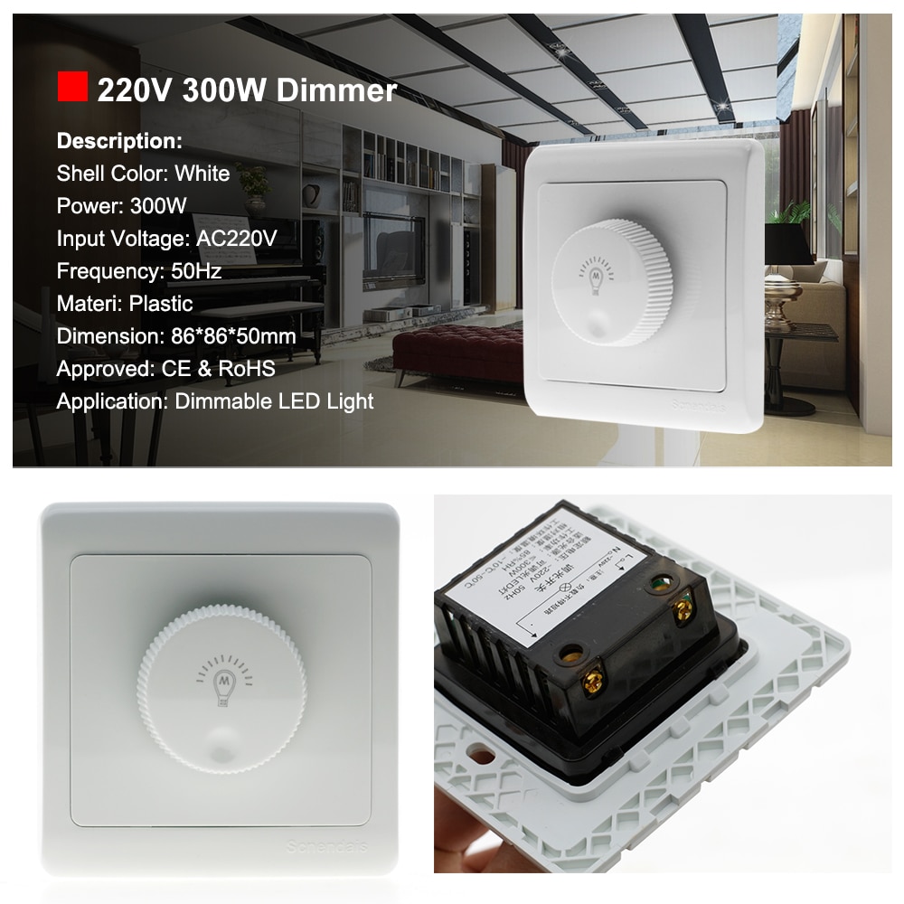
A 220 volt light dimmer switch is a specialized electrical control device engineered to regulate high-voltage alternating current circuits by truncating the sinusoidal waveform to reduce luminous output. According to National Electrical Code (NFPA 70 / NEC), dual-pole or single-pole phase-control dimmers utilized on high-voltage residential or commercial lighting circuits must strictly match the continuous load amperage and ballast compatibility of the fixture to prevent thermal overload. Modern facility managers, automotive test-bench technicians, and advanced home hobbyists frequently encounter high-voltage alternating current (AC) lighting circuits in specialized workshops, commercial bays, and high-output auxiliary illumination setups. Proper implementation demands a rigorous understanding of load calculation, phase-cut topologies, and heat dissipation mechanics. Integrating such devices requires strict adherence to Home Electrical Wiring Diagrams to ensure terminal integrity and mitigate arc-fault hazards.
Wiring Technical Snapshot:
- Core Focus: Phase-cut voltage reduction for high-draw 220V/240V lighting loads.
- Target Scope: High-output commercial fixtures, industrial workspace lighting, and custom high-voltage setups.
- Key Recommendation: Always verify maximum wattage ratings and utilize thermal derating calculations before permanent installation.
Core Principles and Detailed Overview
High-voltage dimming relies on semiconductor switching components such as Triacs or silicon-controlled rectifiers to rapidly chop the AC sine wave, effectively limiting the root-mean-square (RMS) voltage delivered to the load. A standard 220 volt light dimmer switch operates by delaying the trigger pulse during each half-cycle of the alternating current waveform, resulting in a lower average power state across the lamp filaments or LED driver inputs. Unlike standard 120V residential dimmers, 220V applications typically involve split-phase or dual-hot line configurations found in heavy-duty commercial environments, requiring double-pole switching mechanisms that disconnect both live conductors simultaneously. Technicians analyzing these circuits must utilize calibrated digital multimeters and oscilloscope probes to verify phase-angle behavior, load impedance, and harmonic distortion. When evaluating complex multi-load configurations or integrating control modules into existing layouts, consulting structured resources like Appliance and Device Wiring provides critical insights into proper terminal segregation and load balancing.
Key Specifications and Breakdown
| Circuit / Terminal | Standard Wire Color / Gauge | Operational Role & Safety Check |
|---|---|---|
| Hot Line 1 (Line In/Out) | Black or Red (10–12 AWG) | Carries primary 110V–120V leg; verify zero voltage with multimeter in off state. |
| Hot Line 2 / Switched Leg | Red or Striped (10–12 AWG) | Carries secondary synchronized hot leg or switched output; check continuity. |
| Ground / Chassis Bond | Bare Copper or Green (12 AWG) | Provides fault current path to earth; test for low resistance (< 1 ohm) to panel. |
Electrical installations operating at 220 volts or higher require strict verification of device amperage ratings, proper enclosure grounding, and adherence to manufacturer thermal derating guidelines to prevent catastrophic insulation failure. — National Fire Protection Association (NFPA)
Step-by-Step Practical Application and Guidelines
Safely installing and testing a high-voltage dimming circuit begins with completely de-energizing the service panel and locking out the designated circuit breakers. Technicians must strip wire ends to the precise manufacturer-specified length, ensuring no copper conductor remains exposed outside the terminal clamp to prevent accidental short circuits against grounded metal backboxes. When securing conductors into heavy-duty screw terminals or flying leads, torque drivers should be set to exact manufacturer specifications to eliminate high-resistance connections that generate excessive localized heat. After mechanical installation, diagnostic technicians perform preliminary insulation resistance testing before restoring power to check for ground faults or leakage currents. For advanced troubleshooting routines involving control signals and peripheral switching devices, reviewing reference materials within Wiring Troubleshooting ensures methodical fault isolation.
Common Challenges and How to Avoid Them
Audible buzzing, flickering light output, and premature semiconductor failure represent the most frequent complications encountered when deploying high-voltage lighting control hardware. Buzzing typically stems from magnetic core resonance in inductive loads or phase-chop clipping frequencies interacting poorly with incompatible LED drivers or electronic transformers. Technicians can eliminate these issues by ensuring the selected dimmer explicitly matches the load type—specifying trailing-edge (MOSFET) dimmers for capacitive electronic loads rather than traditional leading-edge (Triac) alternatives designed strictly for resistive incandescent bulbs. Furthermore, failing to account for multi-gang thermal derating—where enclosing multiple dimmers in a single wall box reduces their maximum wattage capacity—frequently leads to thermal overload and premature internal fuse destruction.
💬 Frequently Asked Questions
Explore More Wiring Diagrams and Schematics on ReadWires
Mastering complex electrical systems requires access to accurate documentation, reliable schematics, and expert-level diagnostic breakdowns across all automotive and residential applications. Technicians and DIY enthusiasts seeking further technical reference materials can explore the comprehensive library available at ReadWires.com to enhance precision, safety, and efficiency in every wiring project.
Visual Reference Gallery