Introduction
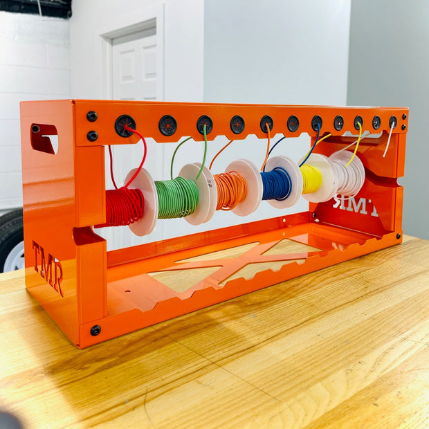
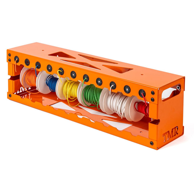
An auto wire organizer is a mechanical management device designed to secure, bundle, and route automotive electrical harnesses securely away from sharp metal edges, moving mechanical components, and extreme heat sources. According to SAE J1128 automotive wiring standards, proper cable routing and containment are essential requirements for preventing insulation degradation, localized short circuits, and premature electrical failure within modern 12V and 24V vehicle architectures. Professional technicians and experienced DIY mechanics utilize these organizers to maintain clean layouts that map directly to complex Vehicle Wiring Diagrams, allowing for rapid fault isolation, reduced voltage drops, and simplified circuit tracing during intense diagnostic procedures.
Wiring Technical Snapshot:
- Core Focus: Structural containment and systematic physical routing of automotive electrical circuits.
- Target Scope: 12V/24V automotive harnesses, aftermarket accessories, and auxiliary component arrays.
- Key Recommendation: Secure all bundled harness runs at intervals not exceeding 12 to 18 inches to prevent vibration-induced fatigue.
Core Principles and Detailed Overview
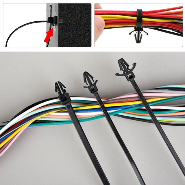
Systematic wire organization transforms chaotic aftermarket and factory harnesses into predictable circuits that integrate seamlessly with professional Wiring Diagram Basics and schematics. Utilizing split-loom tubing, braided sleeving, P-clamps, and zip-tie mounts keeps multi-conductor runs secure against constant engine bay vibration and thermal cycling. When technicians reference Relay and Component Wiring Diagrams, well-organized conduit paths ensure that power feeds, ignition triggers, and ground returns remain visually distinct and physically separated from high-noise signal lines. This physical segregation prevents electromagnetic interference (EMI) and cross-talk between sensitive sensor circuits and high-current power distribution blocks. Furthermore, maintaining structured wire organization preserves wire flexibility, mitigates strain on terminal crimps, and ensures that every individual circuit complies with safe amperage capacities relative to its American Wire Gauge (AWG) size.
Key Specifications and Breakdown
| Circuit / Terminal | Standard Wire Color / Gauge | Operational Role & Safety Check |
|---|---|---|
| Primary 12V Battery Feed | Red / 10 AWG to 4 AWG | Delivers unswitched high current; verify continuity and fuse integrity with a digital multimeter. |
| Chassis Ground Return | Black / 12 AWG to 8 AWG | Completes circuit path to vehicle mass; check for resistance below 0.1 ohms using multimeter resistance mode. |
| Switched Ignition Trigger | Yellow or Blue / 18 AWG to 14 AWG | Activates relays and control modules; inspect terminal security and insulation harness positioning. |
Electrical circuits must be physically secured and protected against mechanical abrasion, continuous vibration, and ambient temperatures exceeding specified insulation ratings to prevent catastrophic short-circuit failures. — National Fire Protection Association (NFPA)
Step-by-Step Practical Application and Guidelines
Implementing an auto wire organizer requires a methodical, step-by-step approach that prioritizes circuit safety, mechanical protection, and adherence to established schematics. Begin by disconnecting the negative battery terminal to eliminate any risk of accidental short circuits during harness manipulation. Next, strip away damaged factory tape and inspect all underlying copper strands for corrosion, oxidation, or thermal damage. Group individual wires according to their specific functional domains, keeping power feeds, data lines, and audio systems segregated to minimize signal interference, referencing specialized layouts such as Audio and Entertainment Wiring Diagrams when necessary. Encase the bundled wire runs inside high-temperature split loom or expandable braided sleeving, securing the entire assembly with UV-resistant cable ties or bolted P-clamps anchored securely to the vehicle body structure. Finally, verify the integrity of every terminal connection and re-test circuit functionality with a digital multimeter before restoring system power.
Common Challenges and How to Avoid Them
Over-tightening zip ties and routing harnesses too close to exhaust headers or steering shafts remain the most frequent errors committed during wire organization projects. Excessive compression from standard plastic ties can crush wire insulation, pinch internal copper strands, and create high-resistance pinch points that generate dangerous localized heat under heavy electrical loads. Technicians must avoid securing wire bundles to sharp sheet metal edges unless rubber grommets or protective edge trim are installed to prevent abrasion from vehicle vibration. Additionally, failing to leave service loops near high-movement components—such as engine blocks and trunk lids—places undue mechanical stress on solder joints and crimp connectors. Addressing these vulnerabilities during the planning phase ensures long-term electrical reliability and prevents intermittent faults that are notoriously difficult to diagnose.
💬 Frequently Asked Questions
Explore More Wiring Diagrams and Schematics on ReadWires
Mastering automotive electrical systems requires continuous reference to accurate documentation, diagnostic guides, and professional schematics. Technicians, DIYers, and enthusiasts can expand their electrical knowledge by exploring comprehensive resources and detailed layouts available across the library at ReadWires.com.
Visual Reference Gallery