Introduction
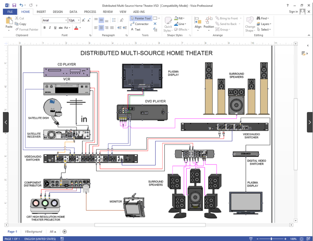
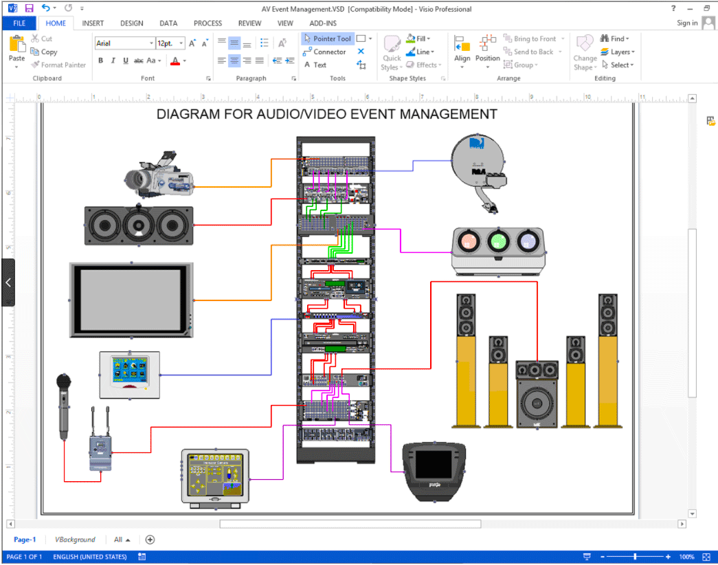
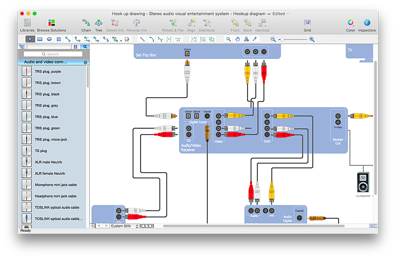
A wiring diagram audio video is a specialized schematic blueprint mapping out the complex interconnections of power, ground, signal, and speaker lines in automotive, marine, and residential entertainment setups. Mastering these schematics prevents costly hardware destruction, ground loops, impedance mismatches, and signal degradation. According to SAE International, adhering to standardized automotive wire color codes and gauge specifications under SAE J1128 standards ensures optimal electrical safety and signal fidelity in mobile electronic installations. Reviewing professional blueprints allows technicians to decode complex entertainment architecture effortlessly. Comprehensive resources for these projects are available within the Audio and Entertainment Wiring Diagrams directory.
Wiring Technical Snapshot:
- Core Focus: Systematic interpretation of audio, video, power, and data signal paths in electrical schematics.
- Target Scope: 12V/24V automotive mobile entertainment and low-voltage residential AV distribution systems.
- Key Recommendation: Always verify polarity and ground continuity with a digital multimeter before powering up any newly wired entertainment circuit.
Core Principles and Detailed Overview
Wiring diagram audio video systems rely on precise graphical symbols to represent amplifiers, head units, coaxial video feeds, unbalanced RCA lines, and balanced XLR or speaker-level outputs. Directing electrical current safely through these networks requires a thorough understanding of resistance, shielding, and voltage drops. Unshielded power wires running parallel to sensitive low-level audio signal cables frequently introduce electromagnetic interference (EMI) or alternator whine into the listening environment. Mechanics and electrical technicians must decode pinout charts, terminal identifications, and harness colors accurately to isolate faults. For broader foundational concepts regarding schematic symbols and standard drawing layouts, consult the references housed in Wiring Diagram Basics.
Key Specifications and Breakdown
| Circuit / Terminal | Standard Wire Color / Gauge | Operational Role & Safety Check |
|---|---|---|
| Constant 12V Battery Power | Yellow / 12 AWG to 14 AWG | Supplies uninterrupted memory and main power; verify inline fuse integrity. |
| Switched Accessory Power | Red / 14 AWG to 16 AWG | Triggers head unit activation via ignition switch; check for voltage drop under load. |
| Amplifier Remote Turn-On | Blue with White Stripe / 18 AWG | Sends low-current 12V trigger signal to external amplifiers; test for short-to-ground faults. |
Proper grounding techniques and conductor sizing guidelines must strictly follow the National Electrical Code (NFPA 70 / NEC) or relevant automotive equipment standards to prevent thermal overload and electrical fire hazards in complex entertainment configurations. — National Fire Protection Association (NFPA)
Step-by-Step Practical Application and Guidelines
Executing a clean installation from a wiring diagram audio video starts with isolating the battery source, identifying harness pinouts, and verifying continuity across every signal path. Begin by cross-referencing the factory or aftermarket installation manual with the physical wire harness, checking wire gauges against the anticipated current draw of multi-channel amplifiers. Strip wire insulation cleanly without nicking the copper strands, and secure all terminal connections using high-grade crimp connectors, heat shrink tubing, or soldered joints where vibration resistance is critical. Route shielded video cables and RCA interconnects away from high-current power distribution paths to eliminate background noise. After completing the physical connections, use a digital multimeter to verify ground resistance values and ensure no unintended shorts exist before reconnecting the primary power source.
Common Challenges and How to Avoid Them
Diagnostic failures in entertainment systems usually stem from incorrect ground placement, reversed speaker polarity, or misinterpretation of proprietary wire color codes. Ground loops occur when system components reference different chassis points with disparate electrical potentials, producing an audible hum or distortion through the speakers. Technicians can eliminate these issues by routing all system grounds to a single, bare metal chassis star-ground location. Furthermore, mismatched speaker impedance loads can cause head units or external amplifiers to enter thermal protection mode or suffer permanent output transistor failure. Careful verification of component resistance ratings against the schematic specifications prevents catastrophic hardware damage during active troubleshooting.
💬 Frequently Asked Questions
Explore More Wiring Diagrams and Schematics on ReadWires
Navigating complex electrical systems requires access to accurate, up-to-date documentation across every automotive, marine, and residential category. Continuous learning and systematic diagnostic methods remain the foundation of professional electrical troubleshooting. Expand technical proficiency by examining specialized schematics, relay layouts, and appliance schematics available directly through ReadWires.com.
Wiring Diagram Schematics & Details