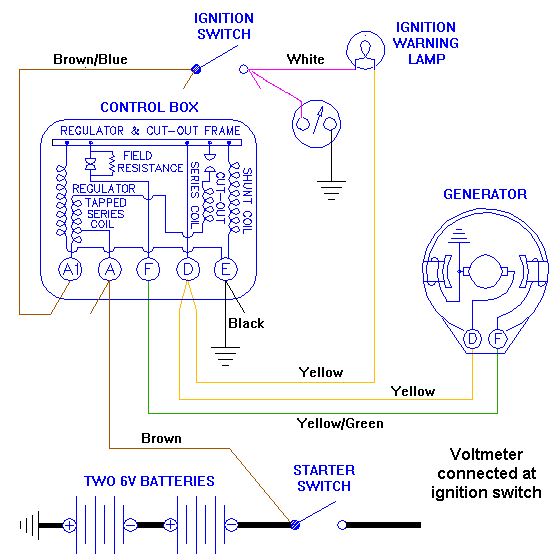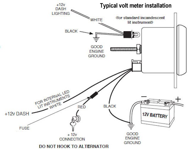
Introduction
Auto voltmeter wiring is the systematic integration of a potential difference measuring device into a vehicle electrical network to monitor alternator charging output, battery health, and accessory bus voltage in real time. According to SAE International, automotive electrical wiring standards dictate precise conductor sizing, insulation ratings, and circuit protection measures to withstand severe thermal, mechanical, and chemical stressors under the hood. Master technicians must correctly interpret Vehicle Wiring Diagrams before altering any dashboard or engine bay power distribution harness. Maintaining rigorous adherence to standardized gauge sizing and proper fuse protection prevents catastrophic short circuits, electrical fires, and sensitive microchip degradation. Integrating a dedicated voltmeter requires disciplined circuit isolation, accurate source identification, and stable grounding methodologies to ensure long-term operational reliability across both 12V passenger cars and 24V heavy-duty commercial applications.
Wiring Technical Snapshot:
- Core Focus: Safe installation and systematic connection of analog or digital voltmeters in automotive electrical grids.
- Target Scope: 12V and 24V DC automotive, marine, and mobile power configurations for DIY mechanics and certified technicians.
- Key Recommendation: Always inline-fuse the positive power lead within six inches of the power source to safeguard the vehicle wiring harness.
Core Principles and Detailed Overview
Auto voltmeter wiring relies on parallel circuit configuration where the meter measures electrical potential difference across two distinct nodes without drawing significant operational current through its own internal circuit board. The fundamental mechanics involve routing a high-impedance display device across switched ignition power and a solid chassis ground, ensuring the reading reflects true system voltage rather than residual battery surface charge. When designing or diagnosing these circuits, technicians frequently cross-reference Wiring Diagram Basics to distinguish between constant battery feeds, switched accessory lines, and pulse-width modulated circuits. Correct polarity is mandatory; reversing positive and negative connections on digital gauges can instantly destroy internal microprocessors, while analog meters may bend indicator needles beyond functional scale limits. Furthermore, integrating panel-mounted voltmeters often requires tapping into existing fuse blocks using dedicated add-a-circuit taps, maintaining factory-grade wire management and avoiding splices prone to high-resistance corrosion.
Key Specifications and Breakdown
| Circuit / Terminal | Standard Wire Color / Gauge | Operational Role & Safety Check |
|---|---|---|
| Positive Power Input (B+ / Ignition) | Red or Yellow, 18-20 AWG | Delivers switched 12V/24V operating voltage; must be protected by an inline 1A to 3A micro-fuse. |
| Chassis Ground (GND) | Black, 18-20 AWG | Provides return path to structural metal; must be terminated at a bare, corrosion-free grounding point. |
| Illumination / Dimmer (Optional) | Blue or White, 20-22 AWG | Taps into dashboard lighting circuit to adjust display brightness during nocturnal driving conditions. |
All low-voltage mobile power circuits must incorporate overcurrent protection sized to protect the conductor ampacity rating against downstream thermal overload. — National Fire Protection Association (NFPA)
Step-by-Step Practical Application and Guidelines
Auto voltmeter wiring execution demands methodical planning, starting with battery disconnection to eliminate accidental short circuits while working near live bus bars and distribution blocks. First, select a clean mounting location on the dashboard or instrument pod, ensuring clear driver visibility and adequate clearance behind the panel for wire routing. Second, identify a switched ignition power source using a digital multimeter to confirm voltage drops to zero when the key is off and reads battery potential when active. Third, route the 18 AWG stranded copper wire through a protective rubber firewall grommet if pulling power from the engine bay alternator or main fuse box, avoiding sharp metal edges and moving steering or suspension components. Fourth, crimp and solder insulated terminal connectors securely, applying marine-grade heat shrink tubing to seal joints against moisture intrusion. Finally, locate a low-resistance chassis grounding stud, remove any paint or oxidation with a wire brush, and secure the ground ring terminal tightly before reconnecting the battery and testing meter calibration against a trusted handheld digital multimeter.
Common Challenges and How to Avoid Them
Auto voltmeter wiring failures frequently manifest as erratic gauge fluctuations, permanent display dimming, or complete inactivity caused by poor grounding, voltage drop, or induced electromagnetic interference. Technicians troubleshooting complex electrical faults often consult Wiring Troubleshooting guides to isolate high-resistance connections and faulty alternator diode ripples that distort digital readouts. A prevalent installation error involves sharing a noisy ground path with high-current devices like blower motors or audio amplifiers, which introduces ground loop voltage offsets and causes the voltmeter display to pulse erratically with bass notes or fan speeds. To eliminate this interference, run the voltmeter ground wire independently back to a dedicated central dashboard ground bus or directly to the negative battery terminal. Additionally, avoid using undersized wire insulation or piercing wire jackets with unsealed probe pins, as moisture infiltration quickly initiates copper oxidation, green crusting, and progressive circuit failure.
💬 Frequently Asked Questions
Explore More Wiring Diagrams and Schematics on ReadWires
Mastering automotive electrical systems requires continuous access to reliable schematics, standardized color codes, and comprehensive technical documentation. Whether configuring accessory instrumentation or diagnosing complex powertrain harnesses, professionals and enthusiasts alike rely on accurate reference materials. Explore thousands of verified schematics, professional guides, and diagnostic layouts by visiting ReadWires.com to elevate every upcoming electrical project with confidence and precision.
Wiring Diagram Schematics & Details