Introduction
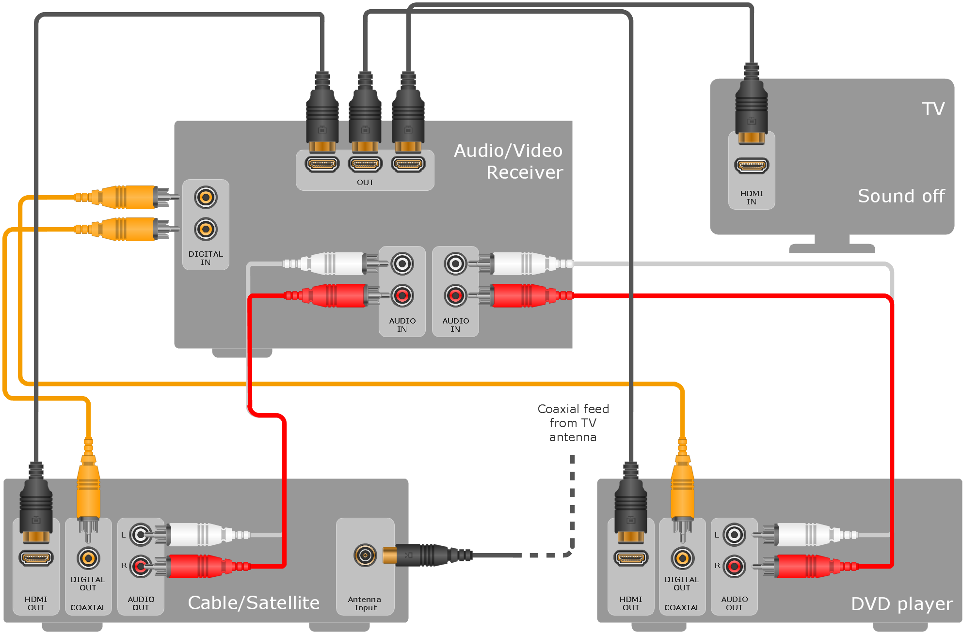
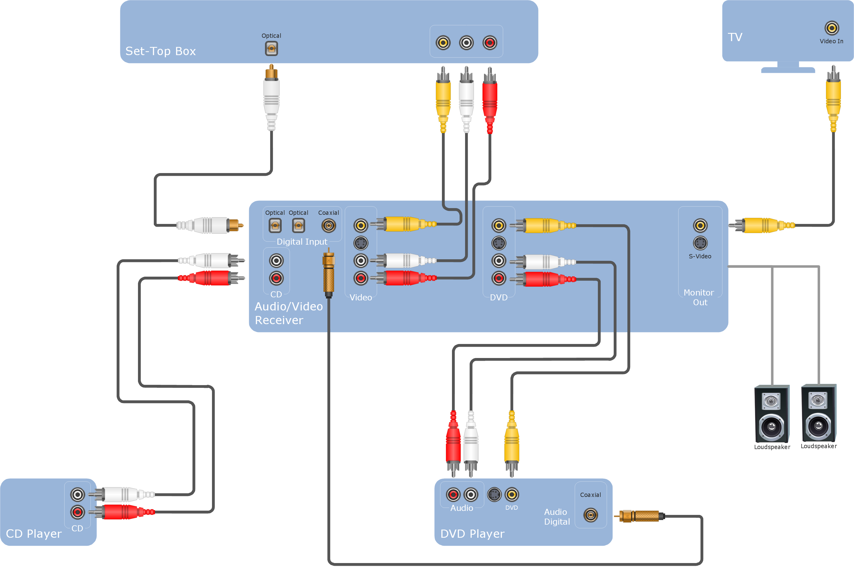
Wiring diagram audio represents a specialized schematical representation mapping the signal routing, power delivery, ground paths, and impedance matching required for mobile and stationary sound systems. According to the Society of Automotive Engineers (SAE J1128 low-voltage primary cable specifications), accurate schematic interpretation prevents voltage drop, signal clipping, and catastrophic thermal overload in high-amperage audio distribution networks. Master technicians rely on these technical layouts to decode complex factory head-unit harnesses, aftermarket amplifier integration modules, multi-channel digital signal processors (DSPs), and passive or active crossover configurations. Navigating these blueprints requires a rigorous understanding of schematic symbology, wire color-coding standards, twisted-pair noise rejection lines, and low-level versus high-level speaker inputs. Whether retrofitting an aftermarket head unit into a modern CAN-bus integrated vehicle or troubleshooting a ground loop hum in an Audio and Entertainment Wiring Diagrams layout, mastering audio diagrams bridges the gap between theoretical electrical engineering and clean, distortion-free sound reproduction.
Wiring Technical Snapshot:
- Core Focus: Decoding and troubleshooting 12V power, remote turn-on, line-level, and speaker output pathways.
- Target Scope: Automotive sound system upgrades, marine audio installations, and multi-zone entertainment wiring.
- Key Recommendation: Always verify factory phase relationships with a phase meter before securing final wire splices.
Core Principles and Detailed Overview
Decoding a wiring diagram audio blueprint requires methodical analysis of discrete schematic layers including power distribution, signal transmission, and transducer output. Ground loops, phase cancellation, and impedance mismatches represent the primary operational failures encountered during system integration, making accurate schematic interpretation essential for isolating electrical faults. Modern schematics delineate constant battery feeds (B+), switched ignition power (ACC), and remote amplifier turn-on leads (REM), each demanding precise wire gauge selection based on total current draw. Furthermore, low-level RCA interconnects and balanced differential lines utilize braided shielding to eliminate electromagnetic interference (EMI) originating from alternator whine or fuel injector pulses. Technicians must cross-reference terminal pinout charts with digital multimeter (DMM) continuity checks to confirm that resistance values across voice coils and crossover networks match manufacturer thresholds. Utilizing structured references found within Wiring Diagram Basics ensures that voltage drops remain within acceptable engineering margins across every branch of the circuit.
Key Specifications and Breakdown
| Circuit / Terminal | Standard Wire Color / Gauge | Operational Role & Safety Check |
|---|---|---|
| Battery Power (B+) | Yellow / 8–4 AWG | Delivers unswitched 12V current to amplifiers; verify in-line fuse integrity within 18 inches of the battery. |
| Remote Turn-On (REM) | Blue with White Stripe / 18 AWG | Provides a low-current 12V trigger signal to power on external amplifiers; check for voltage drop below 10.5V. |
| Speaker Output (Right Front +) | Gray / 16–14 AWG | Carries amplified audio signals to transducer voice coils; measure impedance to ground to prevent short circuits. |
Electrical circuits supplying power to entertainment and auxiliary equipment must incorporate overcurrent protection sized strictly to protect the conductor ampacity rating — National Fire Protection Association (NFPA 70 / NEC)
Step-by-Step Practical Application and Guidelines
Executing a successful audio installation or electrical diagnosis demands a rigorous, sequential workflow starting with power isolation and ending with acoustic phase verification. The primary step involves disconnecting the negative battery terminal to prevent accidental short circuits during harness modification or factory wire tapping. Next, trace every connection on the wiring diagram audio document to physical harness locations, identifying constant power, ignition triggers, and dedicated chassis ground points with a high-impedance digital multimeter. When integrating aftermarket converters or line output converters (LOCs), ensure that high-level speaker signals are properly scaled down without introducing clipping or square-wave distortion into the RCA inputs. Technicians should consult Relay and Component Wiring Diagrams when designing high-draw relay-switched distribution blocks for multi-amplifier setups. Finally, solder or professionally crimp all connections, apply marine-grade heat shrink tubing to seal against moisture ingress, and perform a pink noise frequency sweep to confirm system linearity and absolute phase synchronization.
Common Challenges and How to Avoid Them
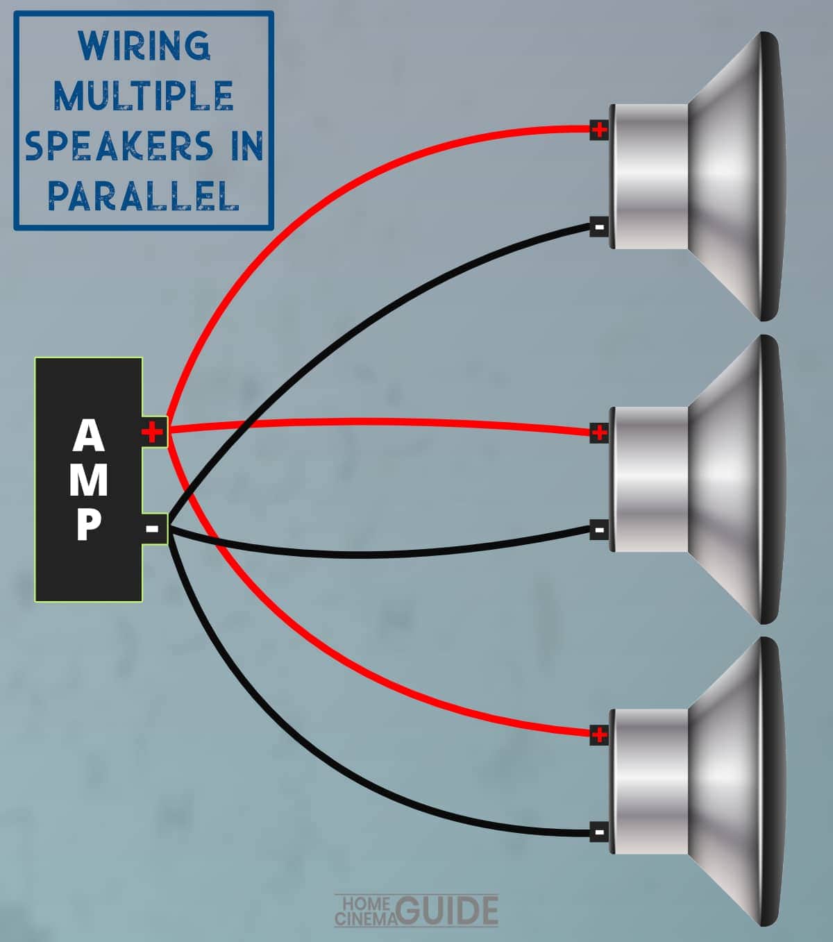
Persistent alternator whine, sudden amplifier protection mode triggers, and weak bass response are the most frequent obstacles technicians face when working with audio schematics. Ground loop interference occurs when multiple components reference different chassis locations with varying electrical resistance, creating an unwanted AC voltage potential across shield grounds. Mitigating this issue requires centralizing all audio equipment grounds to a single, bare-metal chassis point with zero paint or corrosion barriers. Another common error involves reversing speaker polarity during harness splicing, which leads to destructive phase cancellation and complete loss of low-frequency response. Careful adherence to the color codes mapped out in Wiring Troubleshooting guides eliminates guesswork when tracking down intermittent dropouts and blown rail fuses. Technicians must also verify that speaker impedance loads do not drop below the minimum stability threshold specified by the amplifier manufacturer, preventing thermal shutdown and permanent output stage failure.
💬 Frequently Asked Questions
Explore More Wiring Diagrams and Schematics on ReadWires
Mastering complex electrical systems requires continuous access to accurate, standardized, and up-to-date schematic documentation across every domain of modern technology. Exploring the comprehensive resource library hosted at ReadWires.com provides professionals, technicians, and enthusiastic DIYers with the detailed technical pathways necessary to diagnose, repair, and optimize any electrical layout. Access specialized categories covering everything from intricate automotive networks to residential distribution hubs by visiting General and Miscellaneous Wiring Diagrams today.
Wiring Diagram Schematics & Details