Introduction
Wiring diagram continuation refers to the visual conventions and alphanumeric codes used to track electrical circuits as they split across multiple pages, zones, or sub-assemblies in a technical schematic. Understanding this continuation tracking matters because complex modern systems—ranging from residential power distribution governed by the National Electrical Code (NEC/NFPA 70) to multiplexed 12V automotive architectures regulated by the Society of Automotive Engineers (SAE)—rarely fit onto a single sheet of paper. Mastering diagram continuation prevents misinterpretation, ensures safety by accurately mapping voltage pathways, and accelerates diagnostic accuracy during complex system failures.
💡 Technical Key Takeaways:
- Core Focus: Diagnostic schematic and terminal connection layout for Wiring Diagram Continuation.
- Target Scope: Field technicians, automotive DIYers, and residential/commercial electricians.
- Safety Rule: Always disconnect the primary power source/battery terminal and verify zero voltage with a multimeter before touching wires.
Core Concepts and Wiring Fundamentals
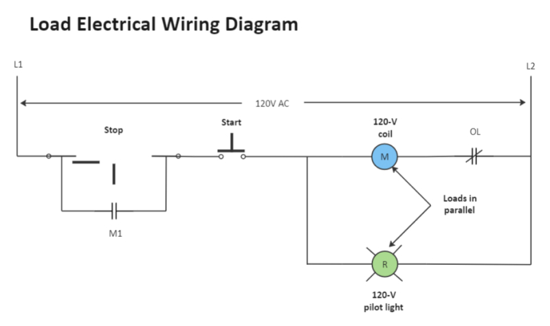
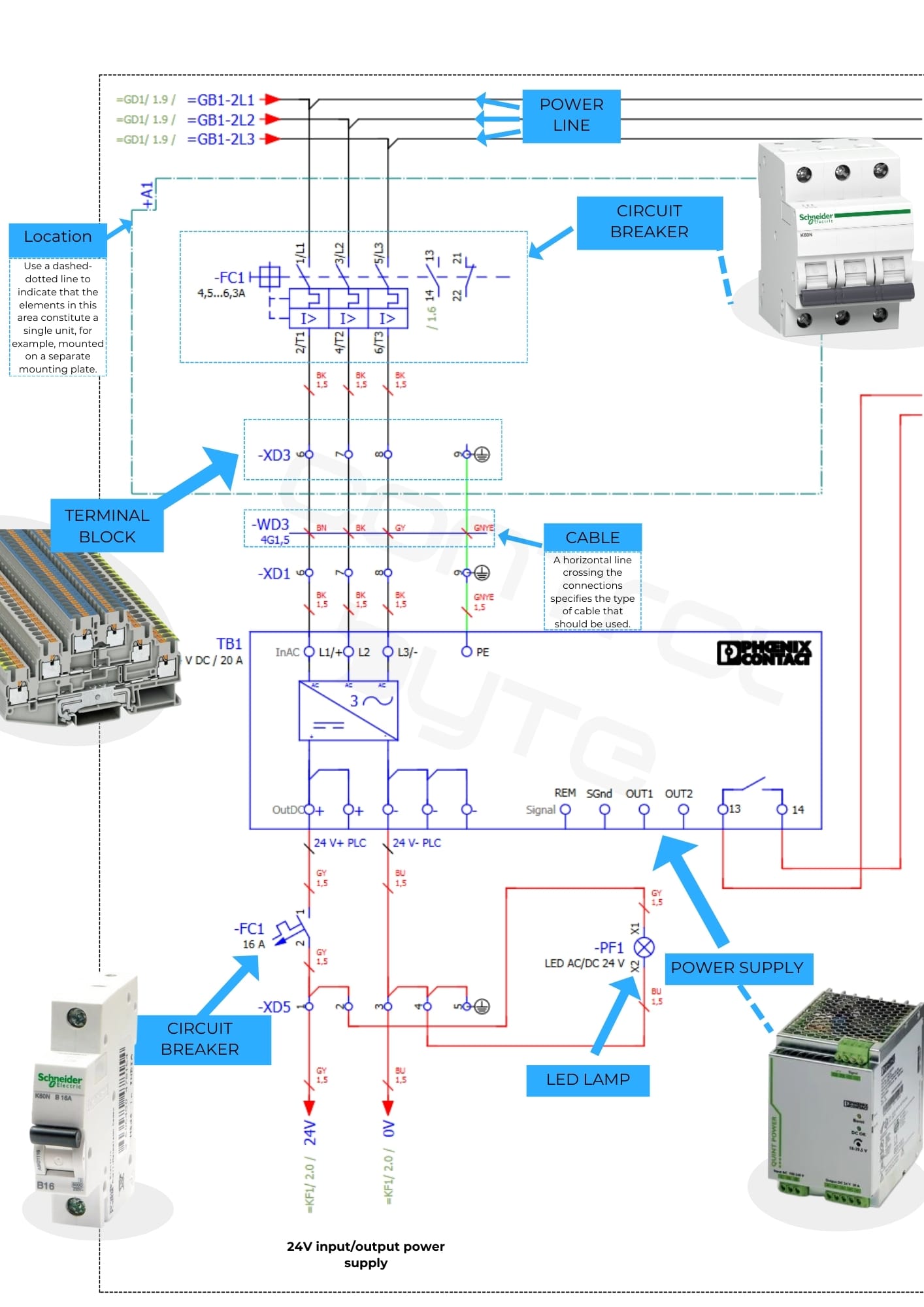
Electrical schematics rely on a standardized language of lines, symbols, and cross-references to represent physical conductors, protective devices, power sources, and loads. A single circuit pathway often begins at a power source, travels through a fuse or circuit breaker, passes via a multi-pin connector or terminal block, and terminates at a ground point or operational load. Because drawings must remain legible, engineers segment these long pathways across different grid coordinates or distinct schematic sheets.
When a trace reaches the edge of a drawing grid, it does not simply vanish. Instead, it terminates in a continuation marker, flag, or coordinate callout that tells the technician precisely where to look on another page to follow that exact conductor. In automotive applications, these references frequently point between engine compartment layouts and cabin fuse panel distributions. In structural installations, they link main service panels to sub-panels detailed in Home Electrical Wiring Diagrams.
[Finding] — Electrical distribution failures and improper circuit tracing remain a leading factor in unprompted equipment downtime across complex industrial and mobile installations, as documented in technical safety reviews by the National Fire Protection Association (NFPA).
Diagram Explanation and Key Components
Reading a continuation symbol requires knowing how to decode alphanumeric grids, line flags, and harness connector pin maps. A continuation symbol typically consists of a geometric box, an arrow, or a letter-number coordinate pair positioned at the severed end of a wire line. For instance, a label reading “Pg 4, C-3” indicates that the conductor continues on page four, specifically within grid sector C-3.
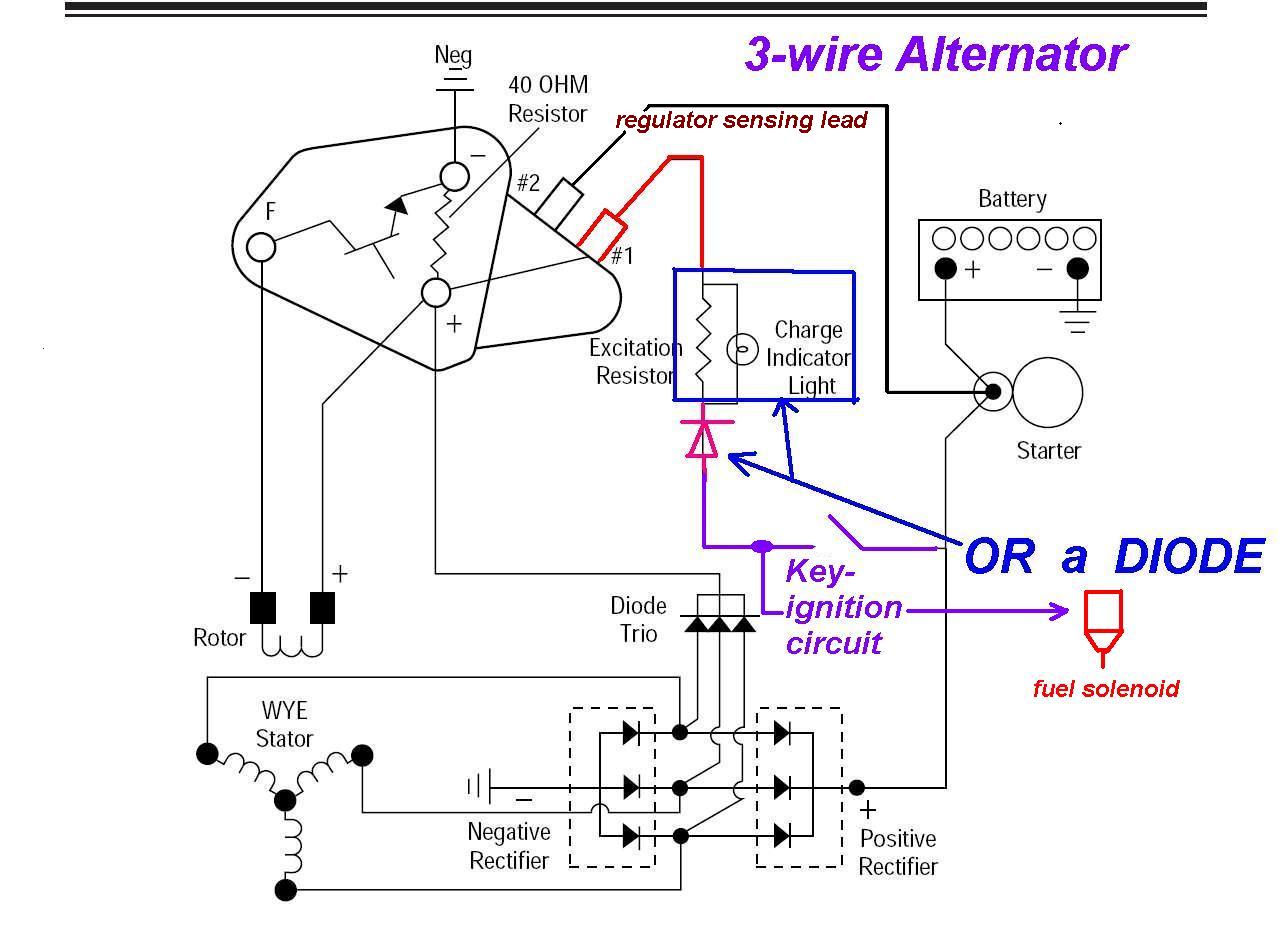
Beyond page coordinates, diagrams utilize destination flags that name the receiving component, connector identifier, or splice pack. Wire color codes also aid continuation tracking, though technicians must account for regional variations. For example, North American automotive wiring typically relies on SAE standards with specific solid colors and tracer stripes, while international systems and residential setups follow distinct local standards such as BS 7671 in the UK or AS/NZS 3000 in Australia. When analyzing internal device pathways detailed in Appliance and Device Wiring, these continuation marks keep control logic separated from high-current power stages.
Common Problems and Troubleshooting Methods
Diagnostic errors often occur when technicians misread continuation markers, assuming a wire dead-ends when it actually bridges to a remote auxiliary module. Typical physical faults along these extended paths include high-resistance corrosion inside intermediate connectors, severed harness sections, or intermittent open circuits caused by mechanical vibration.
A systematic diagnostic process begins by isolating the fault symptom on the primary schematic page. The technician then follows the continuation flags across each sequential sheet, checking voltage drops or continuity with a digital multimeter at every accessible junction point. When tracing signal integrity or low-voltage data lines across complex routing, reviewing Wiring Diagram Basics helps confirm that the technician is interpreting zone grids and wire-tagging conventions correctly before opening up protective wire looms.
Practical Tips and Safety Considerations
Safe electrical work demands rigorous adherence to energy control procedures. Before probing circuits or disconnecting harnesses linked across multiple schematic pages, always de-energize the system, verify zero energy with a calibrated meter, and disconnect the battery in automotive or mobile 12V/24V DC applications. For mains-voltage residential or commercial systems, ensure compliance with local regulations, and use a licensed electrician or qualified technician where regional law mandates professional installation.
Field experience shows that rushing through multi-page schematics leads to misdiagnosed control modules. Always mark off traced lines on a physical or digital copy of the schematic to avoid losing track of complex branching circuits. Protect newly exposed wiring with appropriate heat-shrink tubing and maintain correct wire gauges matching the original manufacturer specifications or applicable electrical codes.
Conclusion
Wiring diagram continuation serves as the essential bridge connecting fragmented schematic pages into a single, cohesive electrical map. By mastering grid coordinates, destination flags, and cross-reference markers, technicians can navigate intricate systems with confidence and precision. Diligent adherence to these reading practices ensures faster diagnostics, safer interventions, and long-term system reliability across automotive, industrial, and residential applications.
Quick Wiring Specifications & Terminal Guide
| Component / Circuit | Standard Wire Gauge | Recommended Protection |
|---|---|---|
| Control & Trigger Signals | 18 – 20 AWG | 5A – 7.5A Inline Fuse |
| Standard Auxiliary Load | 14 – 16 AWG | 15A – 20A Circuit Breaker |
| Main Power Feed / Supply | 10 – 12 AWG | 30A – 40A Heavy-Duty Relay |
Images References