Introduction
Wiring a automotive fan relay is a fundamental electrical task involving the installation of an electromagnetic switch designed to handle high-current cooling fan loads using a low-current control signal. This procedure matters because cooling fans draw substantial electrical current, often exceeding twenty or thirty amps upon startup, which would quickly melt factory dashboard switches or burn out delicate temperature sensors. It is used extensively in engine cooling systems, auxiliary oil coolers, and intercooler setups across modern and vintage vehicles alike. Understanding this installation process improves overall vehicle safety by preventing catastrophic wire harnesses fires, enhances troubleshooting accuracy during overheating events, and ensures long-term reliability of the cooling circuit. Proper relay integration isolates the high-amperage power path directly from the battery to the fan motor while keeping the ignition switch or thermal controller safely isolated on the control side.
💡 Technical Key Takeaways:
- Core Focus: Diagnostic schematic and terminal connection layout for Wiring A Automotive Fan Relay.
- Target Scope: Field technicians, automotive DIYers, and residential/commercial electricians.
- Safety Rule: Always disconnect the primary power source/battery terminal and verify zero voltage with a multimeter before touching wires.
Core Concepts and Wiring Fundamentals
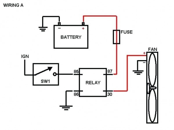
A standard automotive relay operates as a remote-controlled switch utilizing two distinct electrical circuits: a low-power control circuit and a high-power load circuit. The control circuit energizes a small internal electromagnet using minimal current, typically drawn through a toggle switch, thermostat, or engine control unit (ECU). When energized, this electromagnet creates a magnetic field that pulls a physical contact arm closed, completing the high-power load circuit.
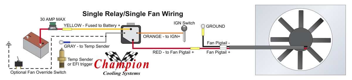
The load circuit bridges the gap directly between the vehicle battery and the electric cooling fan motor, carrying the full operating current required to spin the blades at maximum efficiency. To protect these circuits from overloads and potential short circuits, an appropriately rated fuse must be installed on the main power supply wire as close to the battery source as physically possible. Selecting correct wire gauges, adhering to Society of Automotive Engineers (SAE) specifications, and utilizing weather-resistant connectors prevent voltage drop and thermal degradation across the entire system.
Grounding integrity remains paramount for both circuits. A poor ground connection introduces high resistance, which generates excessive heat and prevents the relay coil from energizing properly or starves the fan motor of required operating voltage. For additional reference on circuit layouts, consult Relay and Component Wiring Diagrams.
Electrical fires in vehicles frequently originate from undersized wiring and un-fused high-amperage accessories added directly to factory switches without intervening relays — National Fire Protection Association (NFPA)
Diagram Explanation and Key Components
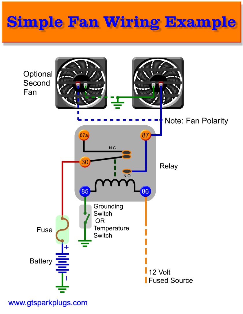
Reading schematics for wiring a automotive fan relay requires recognizing standard terminal numbering conventions established by automotive manufacturers. A standard five-pin or four-pin Bosch-style relay utilizes universal numeric designations molded into the plastic housing: terminal 30 receives constant power from the battery feed, terminal 87 supplies power out to the fan motor load, terminal 85 connects to the control circuit ground or switch trigger, and terminal 86 connects to the switched ignition source or thermal fan switch.
Schematic lines represent physical conductors, where thicker lines typically indicate high-current load paths and thinner lines denote low-current control wires. Color coding varies by region and aftermarket kit manufacturer; for instance, North American aftermarket harnesses often utilize red for battery feeds, black for grounds, blue for fan power, and yellow or green for switch triggers, whereas UK and European installations may follow different conventions. Reviewing standard Vehicle Wiring Diagrams helps clarify manufacturer-specific color coding and factory harness integration points before cutting into existing insulation.
Common Problems and Troubleshooting Methods
Systematic fault-finding when wiring a automotive fan relay involves isolating the control circuit from the load circuit to quickly pinpoint component failure. Typical faults include blown inline fuses, internal relay coil burnouts, corroded spade terminals, and high-resistance grounds caused by painted or rusted chassis mounting points. Technicians frequently observe melted relay sockets resulting from loose terminal crimps that create high electrical resistance under continuous heavy loads.
A structured diagnostic approach begins with verifying battery voltage at terminal 30 using a digital multimeter. Next, check for voltage drop across the fuse and confirm that the control circuit terminals (85 and 86) receive proper signal voltage and continuity to ground when the thermostat or manual switch activates. Listening for an audible click from the relay housing helps verify that the electromagnetic coil is energizing, though a click does not guarantee that the internal high-current contacts (30 to 87) are actually passing power. For complex harness issues, explore resources on Wiring Troubleshooting to refine diagnostic precision.
Practical Tips and Safety Considerations
Best practices for professional installations demand proper wire protection, including split-loom tubing, heat shrink tubing with adhesive lining, and secure zip-tie management away from hot exhaust manifolds and moving pulleys. Always disconnect the negative battery terminal before starting any electrical modification to prevent accidental short circuits, spark generation, or damage to sensitive vehicle computers. Adhering to local codes and professional standards ensures compliance and safety across all jurisdictions, whether working under the US/Canada standard frameworks or international guidelines.
A frequent installation mistake involves mounting the relay upside down or in exposed engine bay locations where water can pool inside the socket housing, accelerating corrosion. Securing the relay firmly to a flat sheet metal surface using a dedicated mounting bracket prevents excessive vibration from fracturing solder joints or terminal pins over thousands of miles of driving.
Conclusion
Mastering the installation and diagnosis of auxiliary cooling circuits ensures optimal engine temperature management and safeguards the entire vehicle electrical infrastructure from thermal overload. By respecting proper wire sizing, utilizing correct fusing, and understanding terminal numbering, installations remain reliable and safe for years of service. For further study on electrical documentation and foundational principles, review Wiring Diagram Basics to expand technical expertise.
Quick Wiring Specifications & Terminal Guide
| Component / Circuit | Standard Wire Gauge | Recommended Protection |
|---|---|---|
| Control & Trigger Signals | 18 – 20 AWG | 5A – 7.5A Inline Fuse |
| Standard Auxiliary Load | 14 – 16 AWG | 15A – 20A Circuit Breaker |
| Main Power Feed / Supply | 10 – 12 AWG | 30A – 40A Heavy-Duty Relay |
Images References