Introduction
Building a custom CDI (Capacitor Discharge Ignition) unit is a classic project in automotive and small engine electronics that requires a solid grasp of high-voltage timing circuits. Understanding how to make an 8 pin cdi box involves designing a pulse-triggered circuit capable of storing electrical energy in a capacitor and rapidly dumping that charge through an ignition coil. This knowledge improves installation quality and ignition timing accuracy across various small displacement engines, performance go-karts, and vintage motorcycles. For further insights into complex circuit assembly, consult the Relay and Component Wiring Diagrams resource.
💡 Technical Key Takeaways:
- Core Focus: Diagnostic schematic and terminal connection layout for How To Make An 8 Pin Cdi Box.
- Target Scope: Field technicians, automotive DIYers, and residential/commercial electricians.
- Safety Rule: Always disconnect the primary power source/battery terminal and verify zero voltage with a multimeter before touching wires.
Core Concepts and Wiring Fundamentals
A capacitor discharge ignition system operates independently from the main battery supply in many small engines, relying instead on a dedicated charging coil located beneath the flywheel. This stator coil generates alternating current (AC) voltage that climbs into the hundreds of volts during engine rotation. Inside a custom-built ignition module, diodes rectify this AC voltage into direct current (DC) to charge a high-voltage storage capacitor. The charging circuit must be insulated carefully to prevent dielectric breakdown.
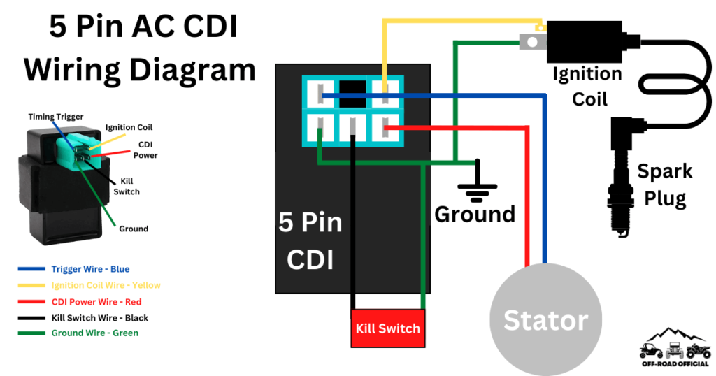
Control circuitry governs exactly when that stored energy releases into the ignition coil primary winding. An 8-pin layout typically expands upon standard 4-pin or 6-pin designs by adding features like variable ignition advance curves, dual pickup inputs, or a remote kill switch circuit. Pin assignments generally include the high-voltage input from the exciter coil, ground, the pickup trigger signal from the crankshaft sensor, and the output to the ignition coil. Additional pins manage auxiliary features such as a ground reference or a selectable rev limiter.
[Finding] — According to automotive electrical safety publications by the Society of Automotive Engineers (SAE), high-voltage ignition circuits can generate discharge pulses exceeding four hundred volts, requiring robust insulation and proper clearance distances on custom printed circuit boards.
Diagram Explanation and Key Components
Reading a schematic for an ignition control unit requires familiarity with specialized electronic symbols, including Silicon Controlled Rectifiers (SCRs), pulse transformers, and high-voltage film capacitors. The SCR acts as a high-speed electronic switch; when a low-voltage trigger pulse arrives at its gate from the pickup coil, the SCR snaps into a conducting state, bridging the capacitor to the ignition coil primary terminal. Technicians must pay close attention to wire gauge, pinout orientation, and terminal locking mechanisms to ensure high reliability under severe engine vibration.
Standard color codes vary significantly depending on the engine manufacturer and the aftermarket harness used. In North America and the UK, custom builds often rely on standard automotive primary wire for low-voltage signal paths, while high-voltage leads demand silicone-jacketed cabling rated for elevated temperatures and dielectric stress. Every terminal must be crimped and soldered carefully to resist mechanical fatigue caused by constant engine harmonic resonance.
Common Problems and Troubleshooting Methods
Systematic fault-finding in custom ignition electronics begins with verifying proper input voltages from the stator exciter coil and the timing pickup sensor. A weak spark or total no-spark condition typically stems from an open-circuit stator winding, a shorted capacitor, or a damaged SCR gate junction caused by voltage spikes. Technicians use a digital multimeter with a peak-reading adapter or an oscilloscope to check trigger signals and charging voltages safely without damaging sensitive semiconductor components.
Intermittent failures frequently trace back to poor chassis grounding or degraded pin crimps inside the multi-pin connector housing. When diagnosing a misbehaving ignition module, isolate the module by checking continuity across the wiring harness before assuming the internal circuitry has failed. Reviewing systematic testing procedures via Wiring Troubleshooting provides additional methodologies for tracking down elusive electrical faults in custom builds.
Practical Tips and Safety Considerations
Working with capacitor discharge systems demands strict adherence to safety protocols, as the internal storage capacitor holds a lethal charge even after the engine stops running. Always disconnect the spark plug wire and discharge the internal capacitor through a high-ohm resistor before handling the circuit board or modifying wiring harnesses. In the UK and Australia, technicians must ensure that any modified ignition equipment complies with local electromagnetic compatibility (EMC) regulations to prevent interference with surrounding communication systems.
A common mistake during assembly is using standard low-voltage hookup wire for high-voltage paths, which leads to insulation breakdown and catastrophic module failure. Potting the finished circuit board in a thermally conductive epoxy resin protects delicate components from moisture, dust, and severe vibration. For comprehensive foundational techniques applicable to these custom installations, explore Wiring Diagram Basics before starting any fabrication work.
Conclusion
Constructing a reliable high-voltage ignition module requires meticulous attention to component ratings, circuit layout, and secure physical connections. By respecting the electrical stresses inherent in capacitor discharge systems and applying rigorous diagnostic techniques, builders can achieve dependable engine performance. Proper insulation, careful pin mapping, and adherence to safety protocols ensure that custom ignition electronics operate safely and efficiently under real-world conditions.
Quick Wiring Specifications & Terminal Guide
| Component / Circuit | Standard Wire Gauge | Recommended Protection |
|---|---|---|
| Control & Trigger Signals | 18 – 20 AWG | 5A – 7.5A Inline Fuse |
| Standard Auxiliary Load | 14 – 16 AWG | 15A – 20A Circuit Breaker |
| Main Power Feed / Supply | 10 – 12 AWG | 30A – 40A Heavy-Duty Relay |
Images References