Introduction
Mastering how to get turn signal and brake light working together is essential for maintaining road safety and legal compliance in 12V and 24V DC automotive electrical systems. This operational challenge arises because many vehicles, particularly those utilizing combined stop and turn filament bulbs or specialized trailer towing configurations, must route two distinct operational signals through a single physical conductor. Understanding how these circuits interact improves diagnostic accuracy, prevents dangerous lighting failures, and ensures proper signaling on the road. For additional resources on vehicle electrical architecture, consult Vehicle Wiring Diagrams.
💡 Technical Key Takeaways:
- Core Focus: Diagnostic schematic and terminal connection layout for How To Get Turn Signal And Brake Light Working Together.
- Target Scope: Field technicians, automotive DIYers, and residential/commercial electricians.
- Safety Rule: Always disconnect the primary power source/battery terminal and verify zero voltage with a multimeter before touching wires.
Core Concepts and Wiring Fundamentals
Vehicle lighting systems rely on a Direct Current (DC) power source supplied by the battery and alternator, protected by fuses and controlled through switches and relays. The primary complication in dual-function lighting occurs when a single bulb serves as both the brake light and the directional indicator. In standard separated systems, distinct circuits feed independent filaments or LEDs. However, combined systems require a dedicated circuit logic to merge these functions without causing electrical feedback.
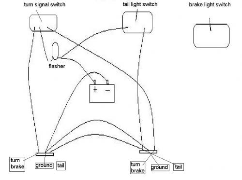
When the brake pedal is depressed, voltage travels from the stop lamp switch directly to the rear lamp circuit. Simultaneously, activating the turn signal switch sends a flashing pulsed voltage down the same wire. Without proper circuit isolation, operating the turn signal would cause the brake lights to flash, or worse, backfeed voltage into the hazard and turn signal flasher module. To resolve this, modern towing setups and specialized conversions utilize a trailer converter—often called a taillight converter—to translate separate input signals into a unified output, or vice versa depending on the vehicle platform.
Ground integrity remains paramount in these multi-function circuits. A compromised chassis ground near the rear lamp assembly creates high resistance, forcing return current to find alternative paths through adjacent filaments. This phenomenon causes erratic glowing, ghosting, and synchronization failures between the brake and signal lights. Technicians must verify low-resistance paths back to the battery negative terminal before condemning switches or control modules.
Vehicle lighting and signaling system failures consistently rank among the most common equipment-related citations issued during roadside safety inspections — Federal Motor Carrier Safety Administration (FMCSA)
Diagram Explanation and Key Components
Reading a schematic for combined lighting circuits requires familiarity with standard automotive symbols, line types, and regional color codes. According to standards established by the Society of Automotive Engineers (SAE) in North America, or BS standards and equivalent European specifications internationally, wire insulation colors vary significantly. North American wiring frequently utilizes green for the right turn/stop signal and yellow for the left turn/stop signal, whereas European and UK applications often follow different color designations.
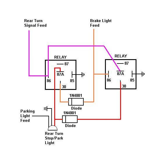
Schematics represent switches as mechanical contact symbols, fuses as jagged resistance lines, and lamps as circles containing filament loops or diode symbols. When examining a Wiring Diagram Basics guide, tracing the lines reveals how power flows from the multi-function steering column switch and the brake pedal switch into the lighting control module or converter box. Diodes appear as arrowheads pointing in the direction of allowed current flow, serving as one-way valves that prevent brake current from feeding back into the turn signal flasher circuit.
Understanding connector pinouts is equally critical. Corrosion inside multi-pin trailer plugs or body-to-chassis harness connectors frequently disrupts the delicate balance required for combined lighting. Technicians must cross-reference pin identification letters and numbers against manufacturer documentation to ensure power, ground, and signal wires align correctly across the connection interface.
Common Problems and Troubleshooting Methods
Systematic fault-finding in dual-function lighting circuits requires a logical, step-by-step diagnostic process using a digital multimeter and a fused test light. A typical symptom involves the turn signal working normally until the brake pedal is pressed, at which point the indicator freezes or the incorrect lamp illuminates. This behavior almost always points to a grounding failure at the bulb socket or a failing isolation converter unit.
Begin diagnosis by disconnecting the negative battery terminal if physical harness repair is required, then verify fuse continuity for both the turn signal and stop lamp circuits. Next, measure voltage at the bulb socket while an assistant operates the brake pedal and turn signals independently. If voltage fluctuates or appears on the wrong pin, isolate the multi-function switch and check for internal short circuits.
Field experience shows that oxidized bulb sockets and mismatched replacement bulbs—such as installing a single-contact bulb into a dual-contact socket—frequently bridge separate circuits internally. Always inspect the physical bulb base and socket terminals for green corrosion or melted plastic before tearing into the vehicle harness. For broader methodology on isolating electrical faults, review structured procedures in Wiring Troubleshooting.
Practical Tips and Safety Considerations
Working on 12V and 24V DC vehicle electrical systems requires strict adherence to safety protocols to prevent accidental short circuits, blown modules, and electrical fires. Always disconnect the vehicle battery before cutting into main harnesses or installing aftermarket towing converters. When splicing wires, avoid substandard crimp connectors that invite moisture intrusion; instead, utilize heat-shrink butt connectors or solder sealed with marine-grade adhesive heat shrink tubing.
Wire gauge selection must match or exceed the original factory specification, typically ranging from 14 AWG to 18 AWG for standard passenger vehicle lighting circuits. Undersized replacement wire increases circuit resistance and generates excess heat under continuous heavy loads like prolonged braking combined with hazard lights. Additionally, secure all routed harnesses away from sharp sheet metal edges and exhaust components using UV-resistant zip ties and protective loom.
Conclusion
Successfully integrating turn signal and brake light functions relies on meticulous circuit isolation, solid chassis grounding, and accurate interpretation of schematics. By understanding how shared conductors handle multiplexed or combined signals, technicians can diagnose erratic lighting behavior efficiently and safely. Diligent preparation, correct component matching, and adherence to established automotive electrical standards ensure long-term reliability and complete road safety.
Quick Wiring Specifications & Terminal Guide
| Component / Circuit | Standard Wire Gauge | Recommended Protection |
|---|---|---|
| Control & Trigger Signals | 18 – 20 AWG | 5A – 7.5A Inline Fuse |
| Standard Auxiliary Load | 14 – 16 AWG | 15A – 20A Circuit Breaker |
| Main Power Feed / Supply | 10 – 12 AWG | 30A – 40A Heavy-Duty Relay |
Images References