Introduction
Understanding how does a 2 wire alternator work is essential for diagnosing modern and vintage automotive charging systems alike. This dual-circuit configuration strips away unnecessary warning lamp circuits and computer data lines, utilizing only a primary high-current power output and a single voltage-sensing reference conductor. Grasping this stripped-down design improves safety, streamlines troubleshooting accuracy, and ensures reliable battery maintenance across various 12-volt and 24-volt mobile platforms. Technicians encountering these setups frequently reference standard Vehicle Wiring Diagrams to trace power flow accurately from the generator back to the battery.
💡 Technical Key Takeaways:
- Core Focus: Diagnostic schematic and terminal connection layout for How Does A 2 Wire Alternator Work.
- Target Scope: Field technicians, automotive DIYers, and residential/commercial electricians.
- Safety Rule: Always disconnect the primary power source/battery terminal and verify zero voltage with a multimeter before touching wires.
Core Concepts and Wiring Fundamentals
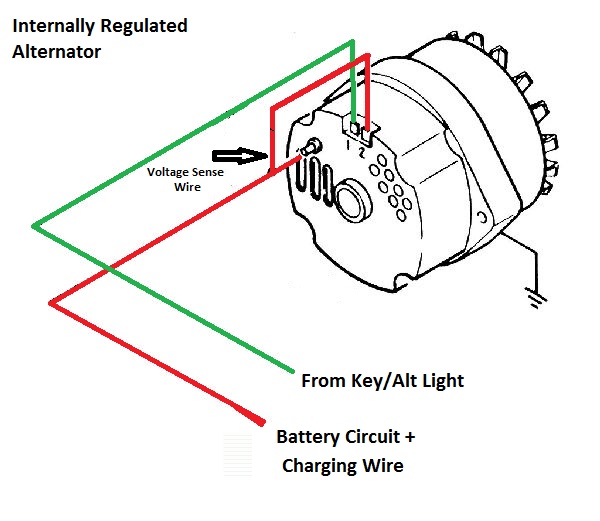
A two-wire alternator utilizes a simplified electrical architecture that combines internal voltage regulation with a minimalist external interface. Unlike older multi-pin regulators, the modern internal regulator on these units manages field current independently once excited, relying solely on two primary external connections.
The first conductor is the main output wire, frequently designated as B+ (Battery Positive). This heavy-gauge cable carries the full generated alternating current—converted to direct current via internal diodes—directly to the starter solenoid terminal or battery positive post. Sizing for this conductor depends on the maximum amperage output of the unit, which varies by manufacturer specification.
The second conductor is the sense wire, often labeled as S or IG. This thinner wire connects the internal voltage regulator directly to a switched power source or the battery itself, providing a reference voltage so the regulator can accurately monitor electrical system load and adjust magnetic field strength accordingly. When studying these circuits alongside auxiliary systems, reviewing Relay and Component Wiring Diagrams helps clarify how switched ignition power interacts with main charging circuits.
Vehicle charging system faults account for a substantial percentage of unexpected roadside disablements, with battery and alternator failures leading the category — Consumer Product Safety Commission (CPSC)
Diagram Explanation and Key Components
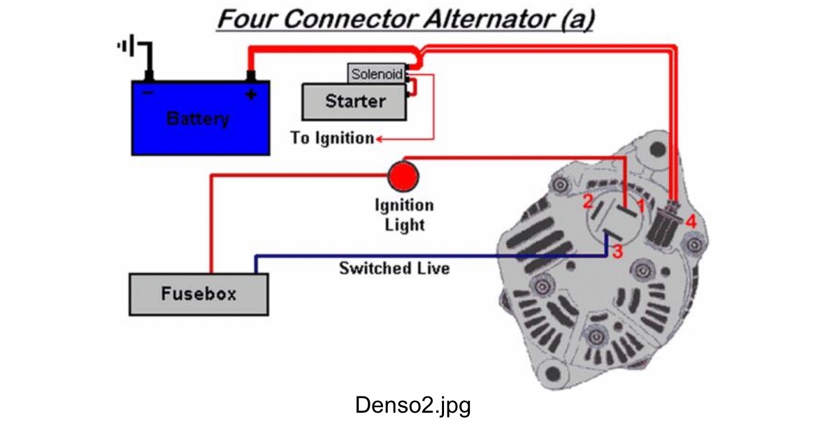
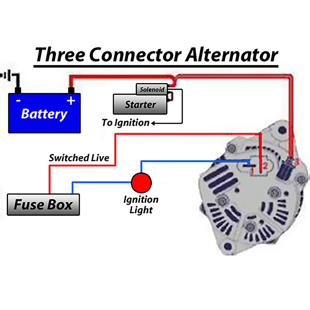
Decoding schematics for a two-wire charging system requires recognizing specific terminal symbols and standardized wire color codes. On typical diagrams, the B+ terminal is represented by a thick line indicating heavy copper cross-section, while the sense wire is drawn as a standard control-circuit line.
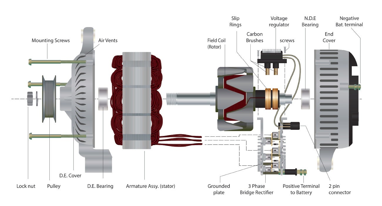
The alternator assembly houses the rotor, stator, diode trio, rectifier bridge, and the solid-state voltage regulator. The stator generates alternating current, which the rectifier bridge converts into direct current. The internal regulator modulates current passing through the rotor windings, controlling the magnetic field strength and output voltage.
The external wiring harness connects the B+ terminal through a high-current fusible link or mega-fuse to protect against catastrophic short circuits. The sense wire connects to a clean 12-volt source, ensuring the regulator reads true system voltage rather than voltage drop across long wiring runs. For technicians learning foundational layout practices, consulting Wiring Diagram Basics provides critical insight into symbol interpretation.
Common Problems and Troubleshooting Methods
Systematic diagnostic procedures for charging failures involve isolating the B+ output circuit from the sense circuit to pinpoint high resistance or open connections. Typical faults include corroded battery terminals, loose B+ stud nuts, breached fusible links, or open-circuit conditions on the voltage sense wire.
Diagnostic assessment begins with a visual inspection of both wires for thermal damage, fraying, or oil contamination. Technicians then perform a voltage drop test across the main output cable while the engine runs under an electrical load, verifying that resistance remains within acceptable limits. If the alternator fails to charge despite a healthy B+ connection, testing the voltage at the sense wire confirms whether the regulator is receiving its necessary reference signal.
When troubleshooting intermittent electrical faults or erratic charging behavior, adopting a structured approach found in Wiring Troubleshooting guides technicians through voltage, resistance, and amperage testing without guessing.
Practical Tips and Safety Considerations
Working on vehicle charging circuits mandates strict adherence to electrical safety protocols due to the constant, un-fused connection between the alternator output stud and the battery. High-current DC systems can deliver severe burns or start electrical fires instantly if grounded accidentally.
Always disconnect the negative battery cable before servicing alternator wiring, replacing terminals, or tightening heavy-gauge fasteners. Ensure replacement wires match or exceed the original factory gauge specifications and utilize proper crimping and heat-shrink insulation to prevent moisture ingress. Regional wiring standards—such as SAE guidelines in North America, BS 7671 in the UK, or AS/NZS 3000 where applicable—dictate correct insulation ratings and protective fusing practices for mobile electrical installations.
Conclusion
Mastering how does a 2 wire alternator work empowers technicians and DIY builders to diagnose charging issues efficiently without relying on complex computer diagnostics. By understanding the distinct roles of the high-current output and the voltage-sensing reference line, electrical faults can be isolated quickly and safely. Proper maintenance of these two critical connections ensures long-term system reliability and optimal battery health across diverse automotive platforms.
Quick Wiring Specifications & Terminal Guide
| Component / Circuit | Standard Wire Gauge | Recommended Protection |
|---|---|---|
| Control & Trigger Signals | 18 – 20 AWG | 5A – 7.5A Inline Fuse |
| Standard Auxiliary Load | 14 – 16 AWG | 15A – 20A Circuit Breaker |
| Main Power Feed / Supply | 10 – 12 AWG | 30A – 40A Heavy-Duty Relay |
Images References