Introduction
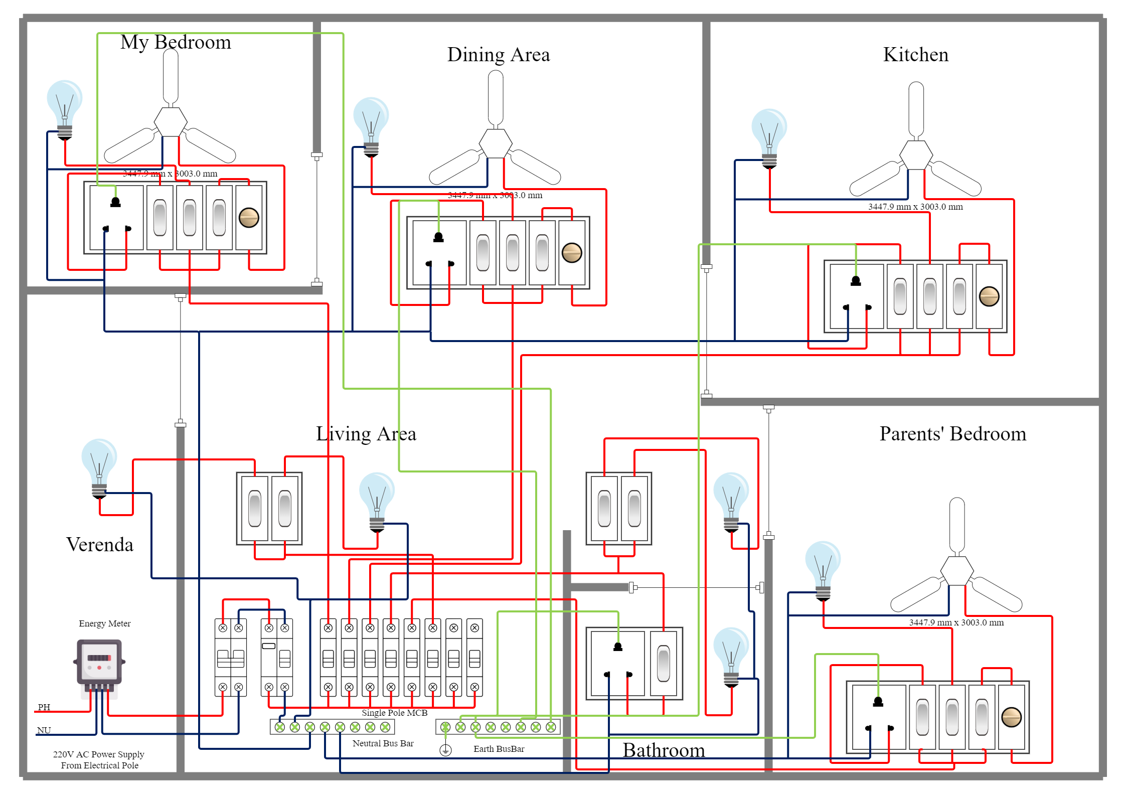
A home electrical diagram is a comprehensive visual blueprint mapping the physical routing, circuit connections, load distributions, and device locations of a residential alternating current power system. Mastery of these schematics ensures safe installations, accurate load balancing, and rapid fault isolation for residential electrical grids. According to the National Fire Protection Association (NFPA 70 / NEC), precise adherence to standardized wiring schematics and circuit identification protocols is mandatory to prevent catastrophic arc faults, circuit overloads, and electrical fires. Professionals and advanced DIY mechanics utilize these blueprints to bridge the gap between abstract power delivery and physical hardware like breaker panels, switches, and outlets. For foundational concepts on reading complex schematics, review the principles detailed in Wiring Diagram Basics before attempting live diagnostics.
Wiring Technical Snapshot:
- Core Focus: Mapping 120V/240V residential branch circuits, neutral paths, and equipment grounding conductors.
- Target Scope: Residential electrical installations, service panels, sub-panels, and dedicated appliance runs.
- Key Recommendation: Always verify zero energy state with a calibrated digital multimeter before tracing physical wires against the diagram.
Core Principles and Detailed Overview
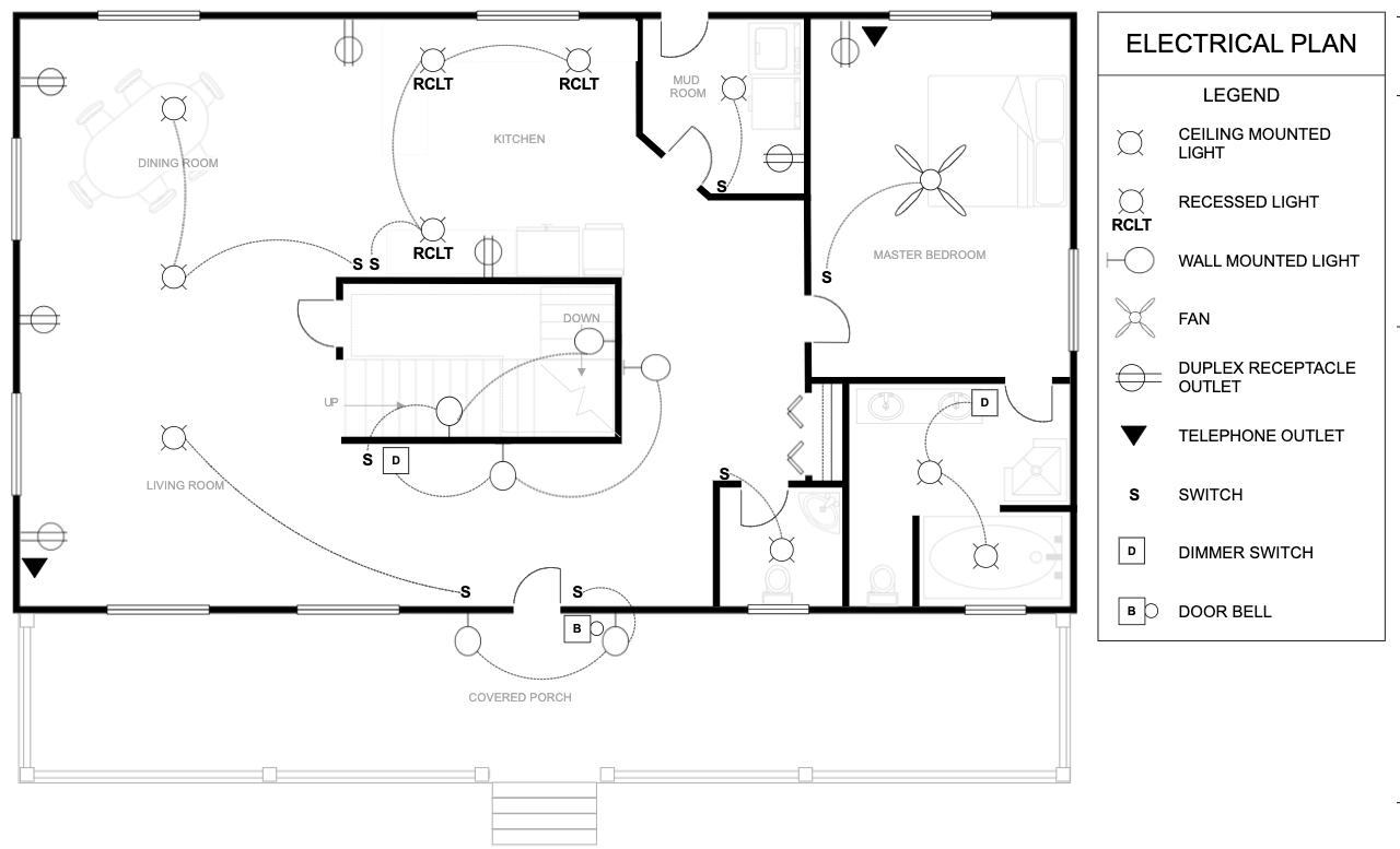
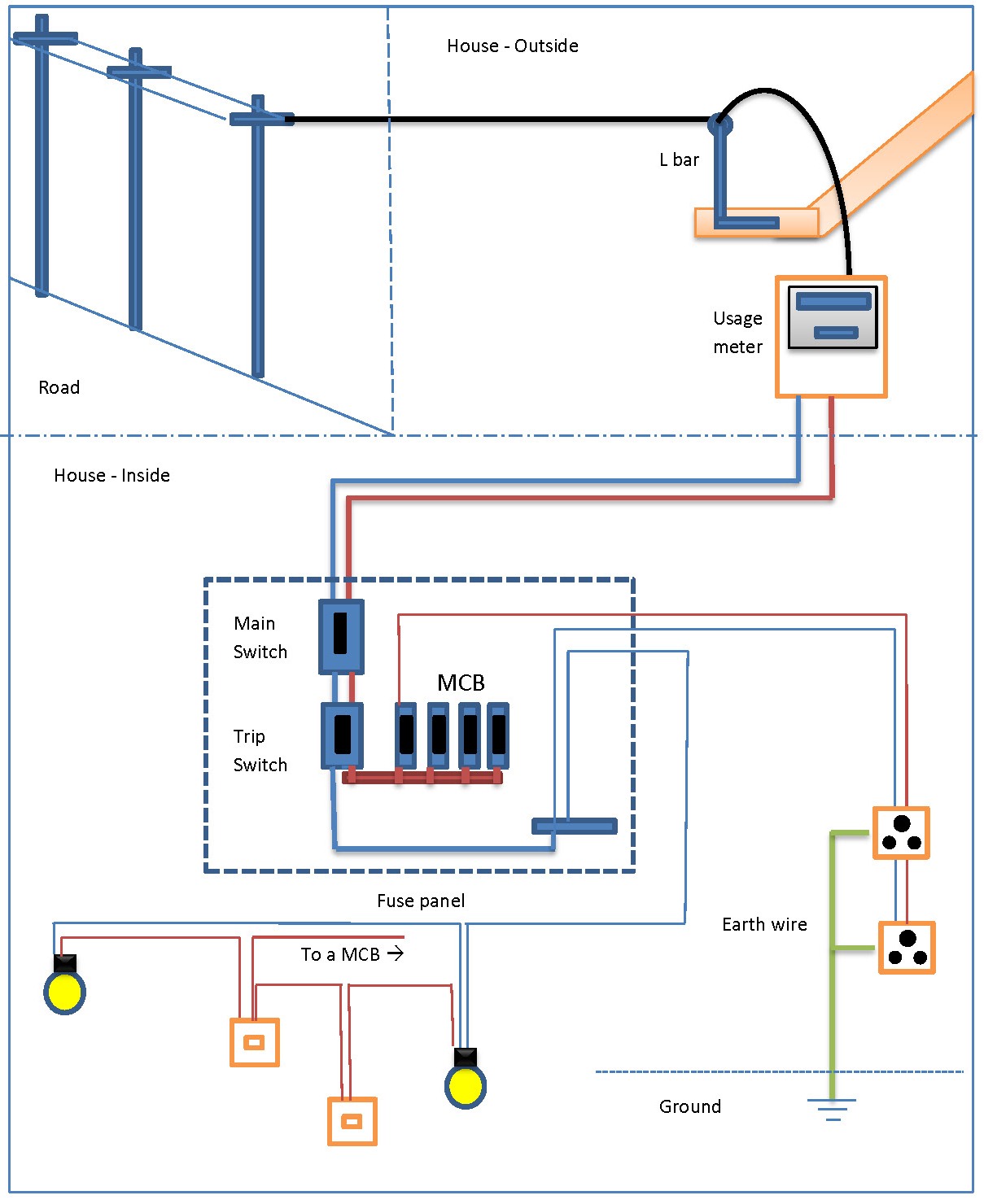
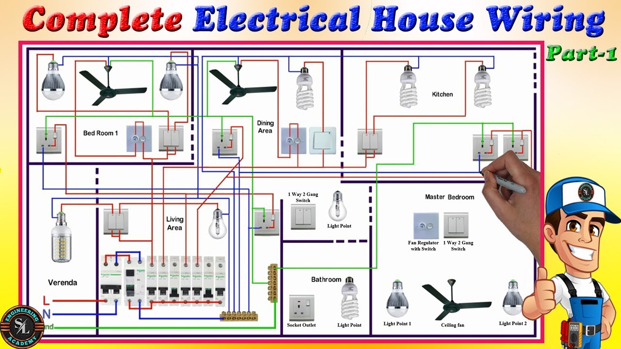
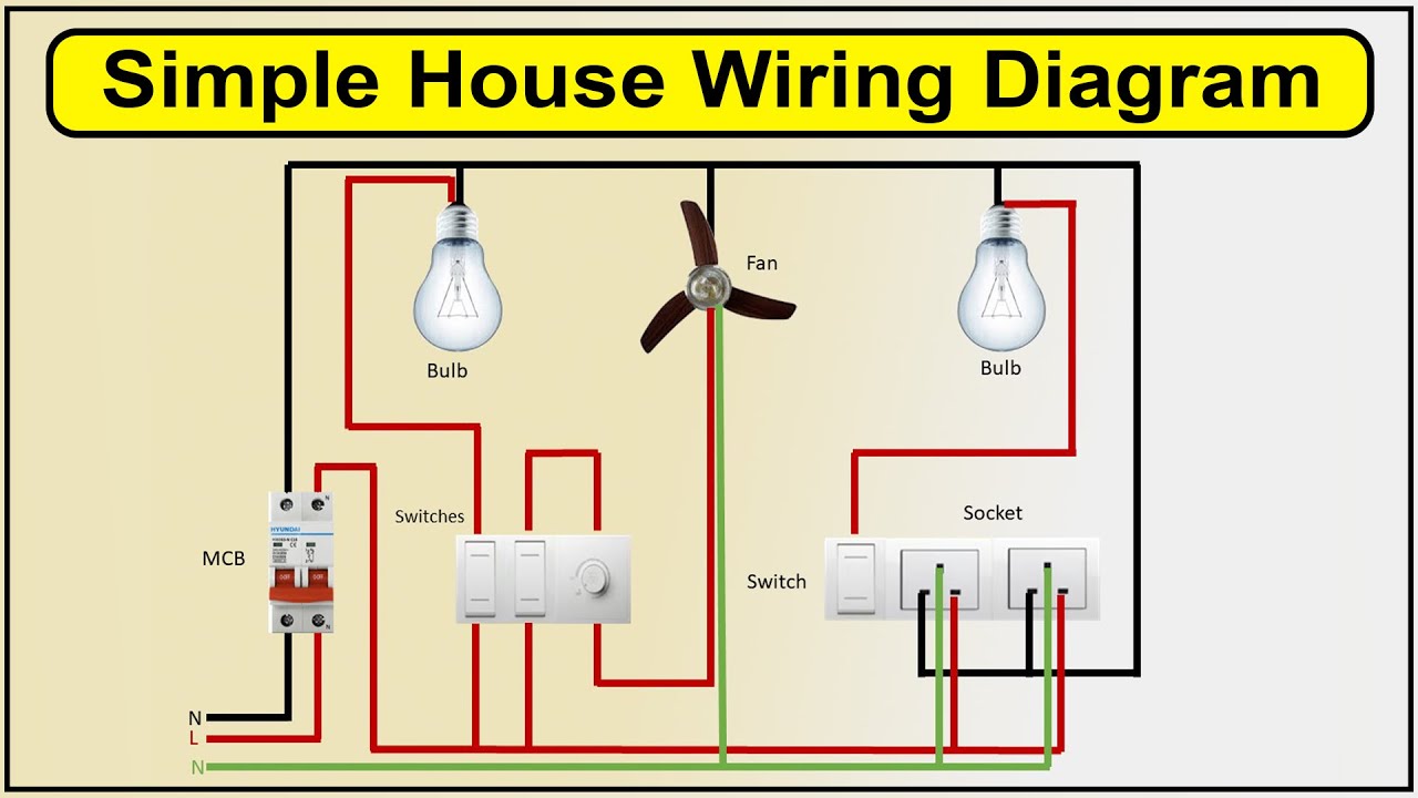
A home electrical diagram utilizes standardized graphical symbols to represent complex electromagnetic pathways, junction boxes, switch legs, and protective overcurrent devices. Direct comprehension of these symbols allows technicians to trace power from the utility service entrance, through the main electrical panel, and down to individual branch circuits without guesswork. Every residential schematic accounts for three essential conductors: the ungrounded hot wire (typically black or red, carrying current), the grounded neutral wire (white, completing the return path), and the equipment grounding conductor (bare copper or green, providing a safety fault path). Understanding how these conductors interact within a breaker panel layout prevents hazardous short circuits and phase imbalances. Detailed architectural floor plans often integrate these electrical layouts to help technicians plan wire pulls, conduit runs, and box fills efficiently.
Key Specifications and Breakdown
| Circuit / Terminal | Standard Wire Color / Gauge | Operational Role & Safety Check |
|---|---|---|
| Hot Conductor (120V Branch) | Black or Red / 14 AWG to 12 AWG | Carries energized current from the breaker; verify zero voltage using a multimeter set to AC volts. |
| Neutral Conductor (Return) | White or Grey / Matched to Hot Gauge | Completes the current circuit path back to the panel; check for continuity and isolated bus connection. |
| Grounding Conductor (Safety) | Bare Copper or Green / 14 AWG to 10 AWG | Provides a low-impedance fault clearance path; test for solid bonding to the main grounding electrode system. |
Strict adherence to manufacturer specifications, local building codes, and National Electrical Code (NEC) standards is mandatory for all residential wiring modifications to eliminate fire and shock hazards — Electrical Safety Foundation International (ESFI)
Step-by-Step Practical Application and Guidelines
Executing an electrical installation or repair safely requires systematically comparing the physical wiring architecture against the home electrical diagram before applying power. The diagnostic workflow begins at the main service panel by locating the specific circuit breaker, locking it out or tagging it out, and confirming power interruption with a non-contact voltage tester. Next, technicians open junction boxes, switch enclosures, and outlet receptacles to inspect wire nut integrity, terminal torque ratings, and conductor insulation for cracking or thermal stress. When troubleshooting unexpected voltage drops or tripped breakers, reference specialized guides found in Home Electrical Wiring Diagrams to isolate faulty splices or overloaded circuits. After completing repairs, continuity checks and insulation resistance testing must be performed prior to closing wall plates and re-energizing the system.
Common Challenges and How to Avoid Them
Misinterpreting outdated architectural schematics, confusing multi-wire branch circuit neutral sharing, and ignoring box fill capacity calculations are the primary causes of residential electrical failures. Technicians frequently encounter legacy wiring where historical color codes do not match modern standards, requiring meticulous wire-tracing with a tone generator and probe kit to prevent cross-wiring. Overloaded neutral conductors in multi-wire branch circuits can also create hazardous voltage spikes if improperly balanced across phases. To address complex home appliance integration or specialized device wiring challenges, consult the expert methodologies available in Appliance and Device Wiring for correct termination procedures. Maintaining disciplined documentation and updating physical diagrams during home renovations eliminates ambiguity for future maintenance personnel.
💬 Frequently Asked Questions
Explore More Wiring Diagrams and Schematics on ReadWires
Mastering residential, automotive, and industrial electrical systems requires access to verified, high-resolution schematics and expert diagnostic documentation. Explore the complete digital library and expand technical expertise across all categories by visiting ReadWires.com for comprehensive wiring resources.
Wiring Diagram Schematics & Details