Introduction
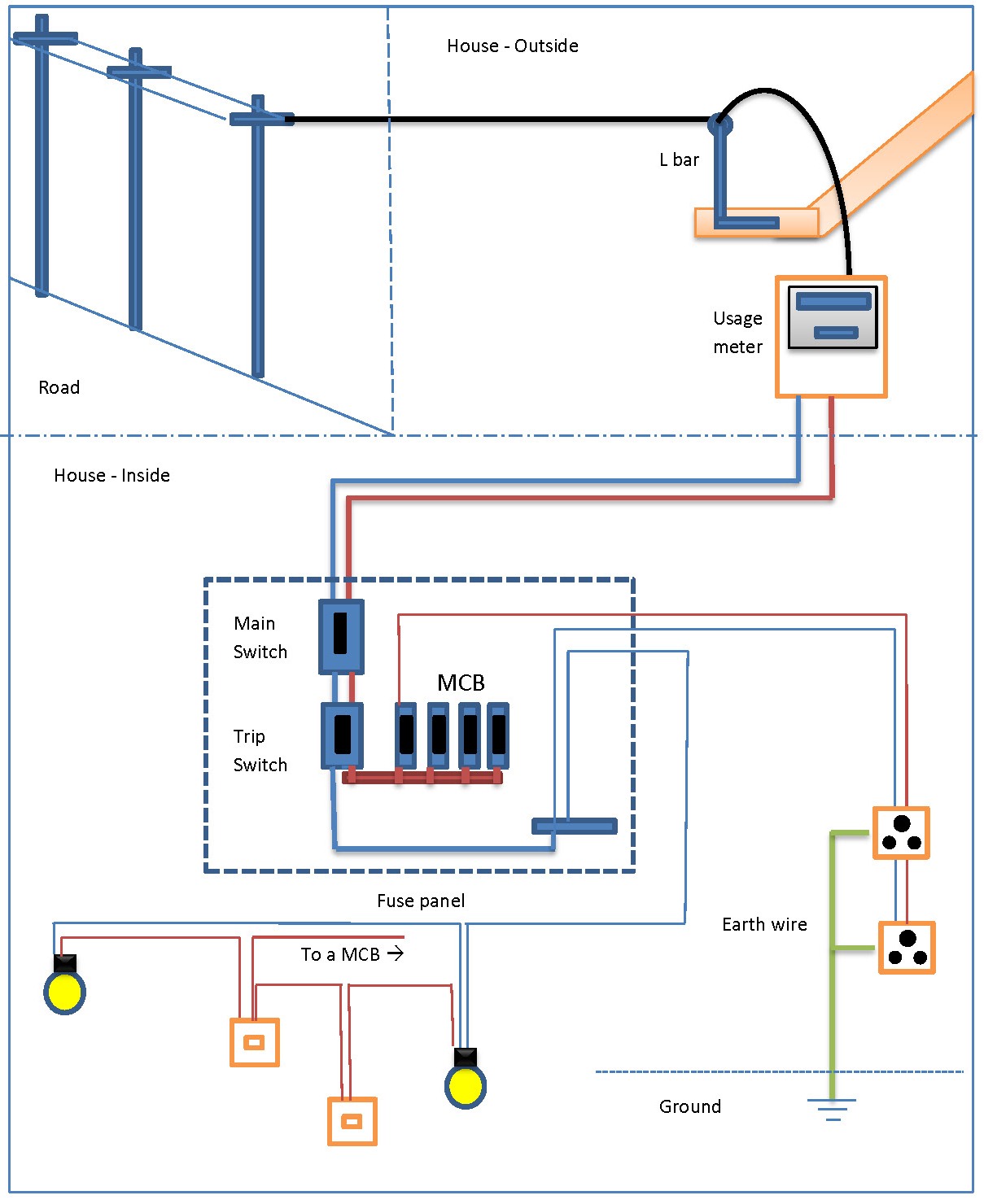
Home wiring explained involves understanding the systematic distribution of electrical energy from the utility supply through service panels to designated branch circuits, load centers, and peripheral devices. According to the National Fire Protection Association (NFPA 70 / NEC), electrical installations must strictly adhere to standardized grounding, conductor sizing, and overcurrent protection protocols to prevent catastrophic thermal overload and arc-fault hazards. Mastering residential power architecture provides foundational knowledge that easily translates to understanding complex low-voltage vehicle networks found in specialized references like Vehicle Wiring Diagrams. Technicians, DIY mechanics, and hobbyists benefit significantly from treating AC residential circuits and DC automotive systems with the same rigorous diagnostic methodology, relying on clear schematics, continuity testing, and systematic voltage drop verification.
Wiring Technical Snapshot:
- Core Focus: Complete breakdown of residential power distribution, conductor paths, and safety circuits.
- Target Scope: Residential electricians, automotive technicians, and advanced DIY electrical troubleshooters.
- Key Recommendation: Always verify zero potential difference with a calibrated digital multimeter before touching exposed terminals.
Core Principles and Detailed Overview
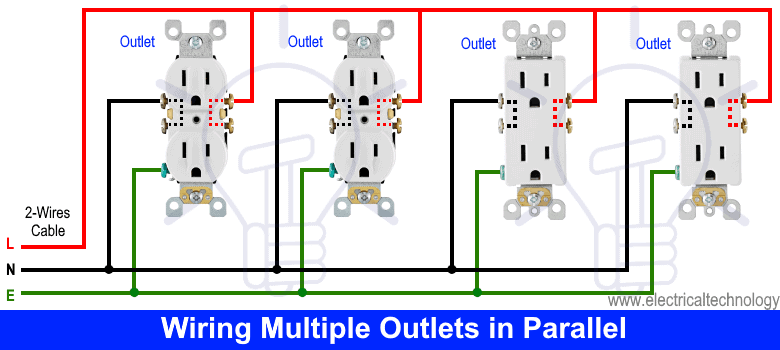
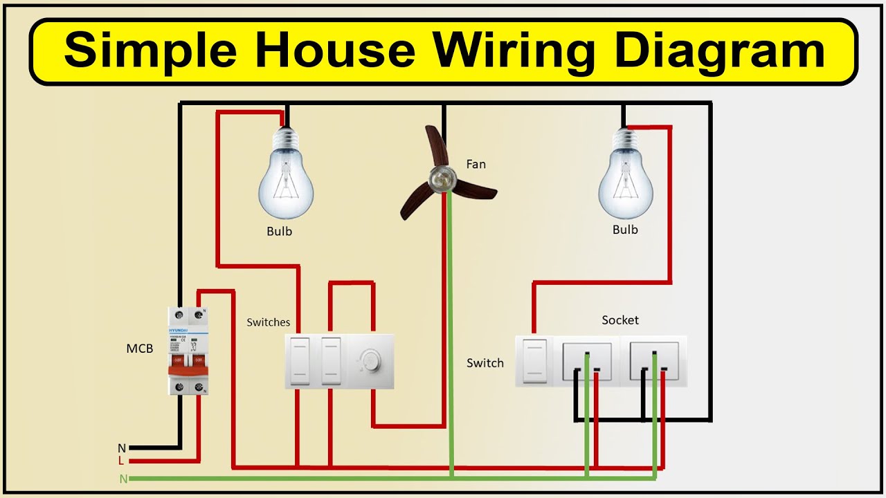
Home wiring functions on a closed-loop system where alternating current flows from a live source through an active load and returns safely via a neutral path, backed up by a dedicated grounding conductor. A thorough review of Home Electrical Wiring Diagrams reveals how individual circuit breakers protect downstream wiring gauges against excessive current draw. Every standard 120V or 240V circuit relies on Ohm’s law ($V = I \times R$) to balance voltage, current, and resistance. When troubleshooting these permanent installations or analyzing secondary power supplies referenced in Appliance and Device Wiring, maintaining strict color-coding discipline—such as black for hot, white for neutral, and bare copper or green for ground—prevents cross-wiring and dangerous short circuits.
Key Specifications and Breakdown
| Circuit / Terminal | Standard Wire Color / Gauge | Operational Role & Safety Check |
|---|---|---|
| Hot Conductor | Black or Red (14 AWG to 10 AWG) | Carries current from the source to the load; verify with non-contact voltage tester. |
| Neutral Conductor | White or Gray (Matched to Hot) | Completes the circuit returning current to the panel; test for open loops under load. |
| Ground Conductor | Bare Copper or Green (Matched) | Provides fault current a safe path to earth; check for low resistance (< 1 ohm) to panel. |
Electrical safety standards mandate that all metallic non-current-carrying parts of a wiring system must be permanently connected to earth ground to limit touch voltages and trip overcurrent protection devices during a fault condition. — Electrical Safety Foundation International (ESFI)
Step-by-Step Practical Application and Guidelines
Executing safe electrical modifications requires a disciplined, step-by-step approach starting at the main service panel and ending at the terminal device. First, isolate the specific circuit by switching the corresponding breaker to the OFF position and securing a physical lockout/tagout device if working in a shared environment. Second, confirm de-energization directly at the target junction box using a reliable multimeter set to measure AC voltage. Third, strip insulation precisely to recommended manufacturer lengths—consulting resources like Wiring Diagram Basics for standard terminal insertion depths—to ensure mechanical security without exposing bare copper outside screw terminals or push-in connectors. Fourth, torque all mechanical wire connectors and terminal screws to exact manufacturer specifications using a calibrated torque screwdriver to eliminate high-resistance joints that cause dangerous thermal hot spots.
Common Challenges and How to Avoid Them
Overloaded branch circuits, loose terminal connections, and improper wire-gauge matching remain the primary culprits behind residential electrical failures and intermittent equipment malfunctions. Diagnostic specialists frequently encounter voltage drops caused by corroded splices or daisy-chained receptacles sharing excessive cumulative loads. Utilizing systematic isolation techniques found within Wiring Troubleshooting helps isolate high-resistance faults before they escalate into thermal events. Mechanics and electricians must verify that circuit breaker amperages match the ampacity ratings of the connected copper conductors, ensuring that 14 AWG wire is never paired with a 20-amp breaker, which violates basic fire safety codes and risks insulation melting.
💬 Frequently Asked Questions
Explore More Wiring Diagrams and Schematics on ReadWires
Expanding diagnostic competence across residential, commercial, and mobile electrical architectures requires access to comprehensive visual references and schematics. Reviewing detailed circuit layouts ensures accurate terminal identification and safe repair execution across every electrical domain. Access the complete library of schematics, reference guides, and system layouts by visiting ReadWires.com today.
Wiring Diagram Schematics & Details