Introduction
Dodge Dakota tail light wiring governs the low-voltage direct current (DC) circuits that supply power to the rear running lights, brake lights, reverse lights, and turn signals of the midsize truck platform. Understanding this electrical architecture matters because rear illumination failures compromise nighttime visibility, invite traffic citations, and create significant rear-end collision hazards. This system is implemented across multiple model generations of the vehicle, interacting with the Power Distribution Center (PDC) and the Central Timer Module (CTM) depending on the production year. Mastering this circuitry improves diagnostic accuracy, prevents unnecessary replacement of expensive lamp assemblies, and ensures reliable operation of vital automotive safety features.
💡 Technical Key Takeaways:
- Core Focus: Diagnostic schematic and terminal connection layout for Dodge Dakota Tail Light Wiring.
- Target Scope: Field technicians, automotive DIYers, and residential/commercial electricians.
- Safety Rule: Always disconnect the primary power source/battery terminal and verify zero voltage with a multimeter before touching wires.
Core Concepts and Wiring Fundamentals
Automotive DC circuits rely on a closed loop where a 12-volt positive battery source feeds current through a fuse panel to a switch or control module, ultimately returning to the vehicle chassis through a designated ground point. On this specific truck chassis, power originates from the battery and passes through specific blade-type fuses housed inside the engine compartment and interior fuse blocks before reaching the rear lamp housings. Voltage drops and intermittent flickering frequently originate within these primary power feeds or at the inline weather-pack connectors located near the rear bumper.
Copper wiring harnesses bundle individual circuits together, utilizing distinct insulation colors to differentiate functions such as stoplamp feed, park lamp supply, and backup illumination. Society of Automotive Engineers (SAE) standards dictate standard automotive wire gauges and insulation ratings suited for under-vehicle environments exposed to road salt, moisture, and thermal cycling. Current flows from the cab switches through the main chassis harness down the driver-side frame rail before branching out to individual bulb sockets via a multi-pin connector.
Ground integrity remains the single most critical factor in maintaining proper illumination levels. A compromised ground path forces return current to seek alternative routes through dual-filament bulb filaments, causing erratic symptoms like dim running lights that brighten unpredictably when the brakes are applied or the turn signals activated. Technicians must routinely inspect these ground eyelets, which are typically bolted directly to clean sheet metal on the inner bed supports or rear frame crossmembers.
[Finding] — According to the National Highway Traffic Safety Administration (NHTSA), lighting and signaling failures account for a substantial percentage of vehicle safety equipment violations and rear-end collisions annually.
Diagram Explanation and Key Components
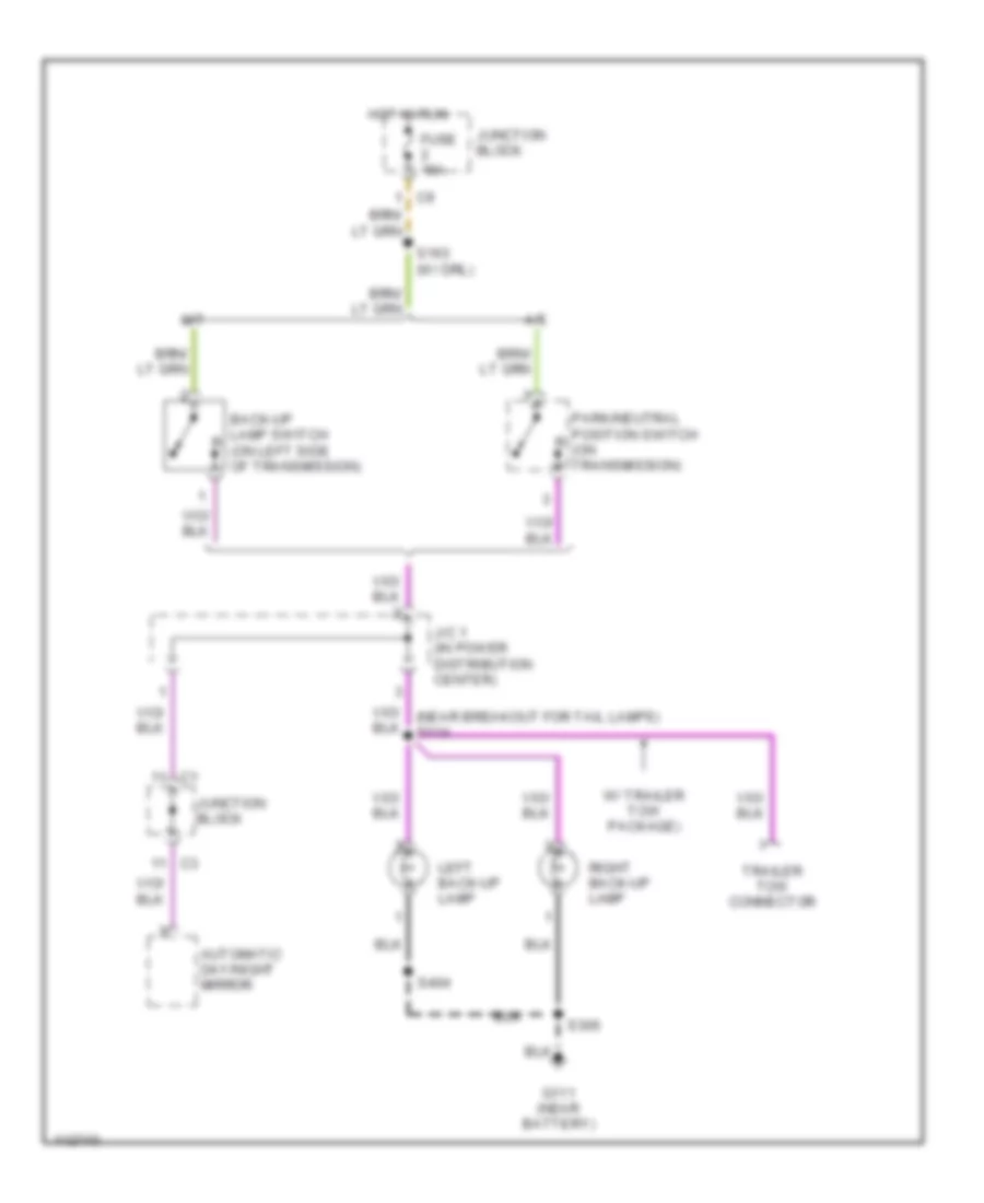
Reading electrical schematics for dodge dakota tail light wiring requires familiarity with standardized automotive symbols representing splices, inline connectors, fuses, and multi-filament lamps. Schematics employ alphanumeric codes to denote wire colors, where abbreviations such as BK/YL represent a black wire with a yellow tracer stripe, and LG/RD denotes light green with a red stripe. Circuit numbers stamped or printed alongside the line diagrams help technicians track an individual wire across multiple pages of a factory service manual.
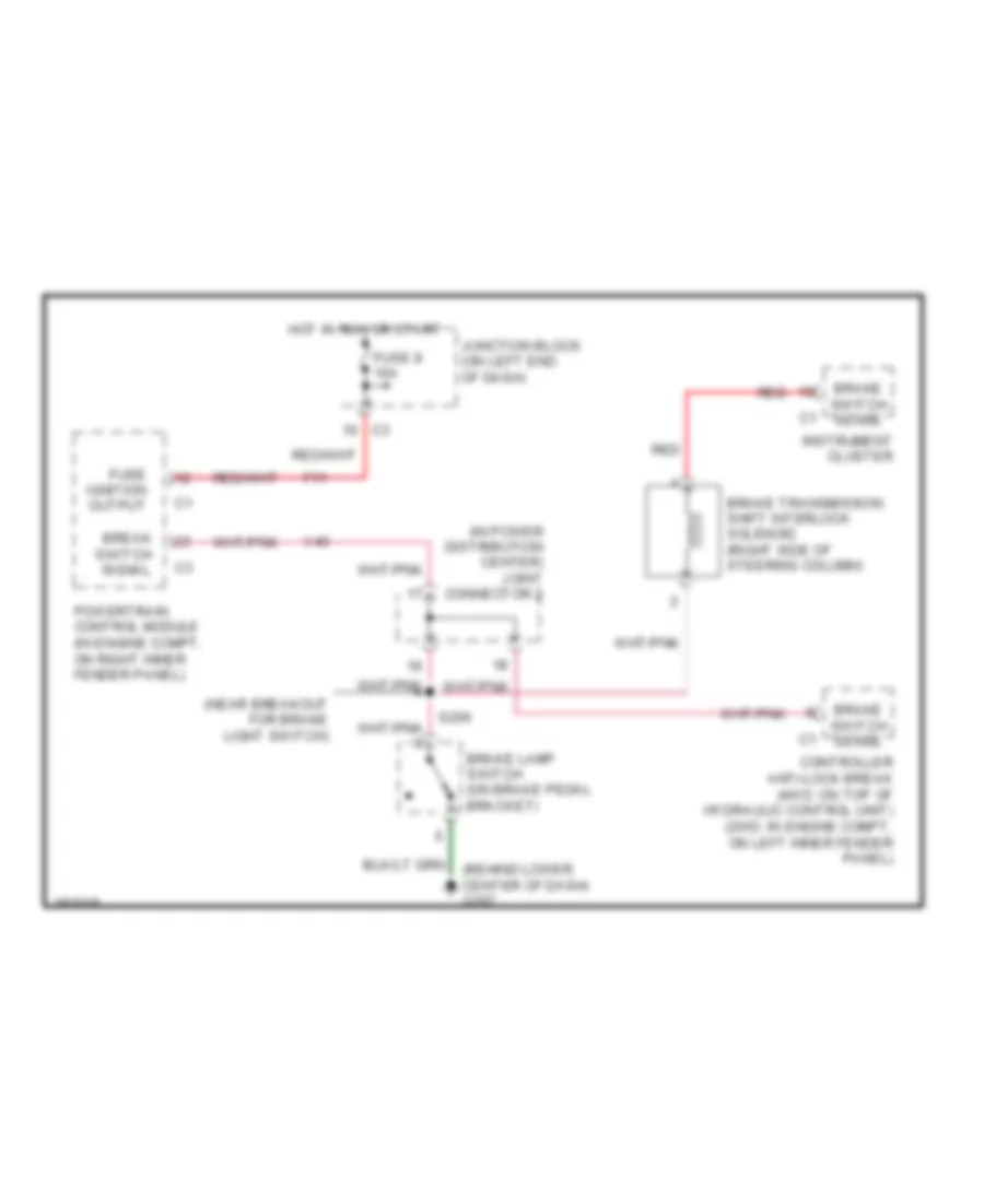
The primary components within this network include the multi-function switch on the steering column, the brake pedal stoplight switch, the electronic flasher module, and the rear lamp circuit board. The multi-function switch directs battery voltage to the rear parking lights simultaneously with the front marker lamps when rotated to the ON position. Meanwhile, the mechanical brake switch closes a distinct circuit whenever the pedal is depressed, sending dedicated 12-volt current directly to the stoplamp filaments.
Connectors are mapped in the schematic with specific cavity numbers, allowing technicians to verify pin tension and continuity at major junction points. For complex diagnostic routines involving integrated body control modules, consulting reference guides found within Vehicle Wiring Diagrams provides the necessary visual framework to isolate faulty control signals from simple mechanical wiring breaks.
Common Problems and Troubleshooting Methods
Systematic fault-finding for dodge dakota tail light wiring begins with a comprehensive visual inspection of the bulb sockets, followed by verification of fuse continuity using a digital multimeter set to resistance or continuity mode. Technicians frequently encounter melted bulb sockets caused by high electrical resistance from corrosion or the installation of incorrect, high-wattage aftermarket bulbs. When a single bulb fails to illuminate while others function normally, the fault usually resides locally at the socket or the bulb filament rather than the main harness.
A structured diagnostic approach eliminates guesswork by testing for voltage drop across suspected high-resistance connections under a live electrical load. The technician connects the multimeter negative lead to a verified chassis ground and probes each cavity of the rear wiring connector while an assistant operates the brake or turn signal controls. If battery voltage registers at the connector but the lamp remains unlit, the issue points directly to a localized ground failure or an open circuit within the lamp assembly circuit board.
For complex symptoms involving erratic trailer towing adapter wiring spliced into the main harness, isolating the aftermarket connections is mandatory. Corrosion inside improperly sealed trailer connectors frequently bridges power and ground circuits, blowing fuses instantaneously. Further insights into diagnosing these multi-circuit anomalies can be reviewed through standard procedures outlined in Wiring Troubleshooting.
Practical Tips and Safety Considerations
Safety protocols require disconnecting the negative battery cable before cutting, splicing, or repairing any automotive wiring harness to prevent accidental short circuits, blown fuses, or module damage. When performing harness repairs, technicians must utilize heat-shrink butt connectors lined with adhesive sealant or solder the joint followed by marine-grade dual-wall heat shrink tubing to prevent moisture ingress and subsequent copper oxidation.
Wire gauge selection must match or exceed the original factory specification—typically 16 to 18 AWG for standard lighting feeds—to prevent excessive voltage drop and thermal overload. Avoid twisting wires together and wrapping them in standard household electrical tape, as road vibration and moisture will quickly degrade the connection, causing intermittent failures. Proper routing away from exhaust components, sharp sheet metal edges, and moving suspension parts ensures long-term reliability of the repaired circuit.
For advanced custom installations or auxiliary lighting integrations, additional relay isolation may be required to protect factory switches from excessive electrical loads. Further foundational principles regarding schematic symbols and line types can be explored in Wiring Diagram Basics.
Conclusion
Dodge Dakota tail light wiring demands methodical inspection, accurate schematic interpretation, and strict adherence to proper repair techniques to maintain vehicle safety and electrical integrity. By prioritizing clean ground connections, weather-sealed splices, and accurate diagnostic testing over component guessing, technicians and DIY mechanics ensure reliable rear illumination under all driving conditions. Proper maintenance of these circuits prevents frustrating electrical gremlins and keeps the vehicle compliant with road safety regulations.
Quick Wiring Specifications & Terminal Guide
| Component / Circuit | Standard Wire Gauge | Recommended Protection |
|---|---|---|
| Control & Trigger Signals | 18 – 20 AWG | 5A – 7.5A Inline Fuse |
| Standard Auxiliary Load | 14 – 16 AWG | 15A – 20A Circuit Breaker |
| Main Power Feed / Supply | 10 – 12 AWG | 30A – 40A Heavy-Duty Relay |
Images References