Introduction
A diagram of a 20amp house breaker maps the physical and electrical connections between a residential service panel, the overcurrent protection device, and the branch circuit conductors supplying high-demand loads. This visual schematic matters because it dictates how residential electrical currents flow safely from the utility supply to kitchen appliances, laundry rooms, and dedicated workshop receptacles. Understanding this layout is essential for ensuring safety, maintaining code compliance, and executing accurate diagnostics during residential modifications. Reviewing foundational layouts found in Home Electrical Wiring Diagrams helps clarify how individual circuit breakers integrate into the broader household distribution grid. Every technician and DIY enthusiast must grasp these foundational layouts to prevent catastrophic electrical failures, equipment damage, and personal injury.
💡 Technical Key Takeaways:
- Core Focus: Diagnostic schematic and terminal connection layout for Diagram Of A 20Amp House Breaker.
- Target Scope: Field technicians, automotive DIYers, and residential/commercial electricians.
- Safety Rule: Always disconnect the primary power source/battery terminal and verify zero voltage with a multimeter before touching wires.
Core Concepts and Wiring Fundamentals
A standard 20-ampere household circuit relies on a closed-loop system comprising a hot conductor, a neutral conductor, and a grounding conductor routed from the breaker panel to the point of use. The hot conductor carries current under potential voltage from the breaker terminal to the load, while the neutral conductor provides the return path back to the service panel neutral bar. Meanwhile, the equipment grounding conductor provides a low-impedance path to ground for fault currents, tripping the protective device during a short circuit.
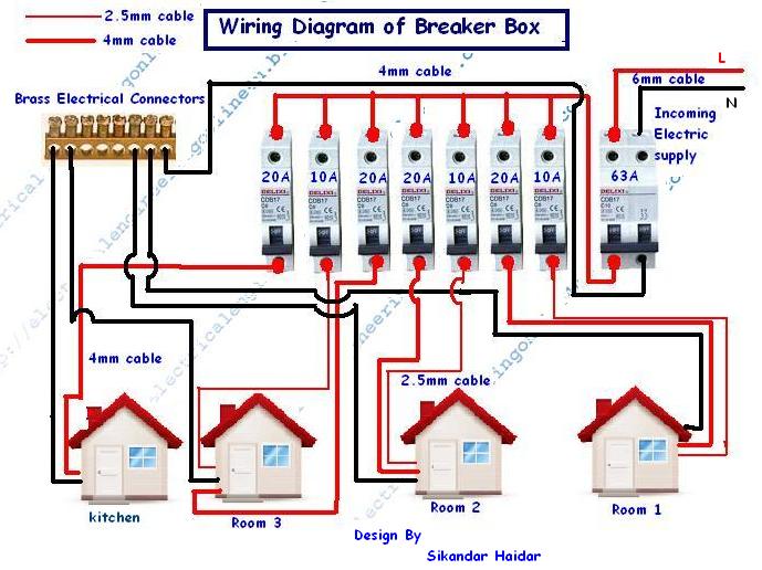
Within the distribution panel, the 20-ampere single-pole breaker snaps onto a bus bar carrying 120 volts alternating current in North American systems, or corresponding line voltages in international jurisdictions. In the United States and Canada, the National Electrical Code (NEC/NFPA 70) or the Canadian Electrical Code (CEC) mandates the use of 12 AWG (American Wire Gauge) copper conductors as the minimum sizing requirement for a 20-ampere branch circuit. Conversely, regions adhering to British Standards (BS 7671) or Australian/New Zealand Standards (AS/NZS 3000) utilize metric conductor sizing, typically 2.5 square millimeter copper cables, paired with appropriate circuit breaker ratings and distinct regional wire color codes.
Circuit breakers operate via dual protection mechanisms: thermal bimetallic strips that bend under sustained moderate overloads and magnetic trip coils that react instantly to severe short circuits. When current exceeds the 20-ampere threshold for a designated duration, the internal mechanism trips, mechanically separating the contacts and interrupting power flow. This mechanical interruption prevents downstream wiring from exceeding its thermal capacity, thereby avoiding insulation breakdown and structural fires.
Overcurrent protection devices such as circuit breakers are designed to protect building wiring conductors from dangerous overheating caused by overloads and short circuits, as specified by the National Fire Protection Association (NFPA). — NFPA 70 (NEC)
Diagram Explanation and Key Components
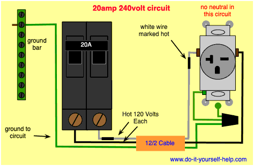
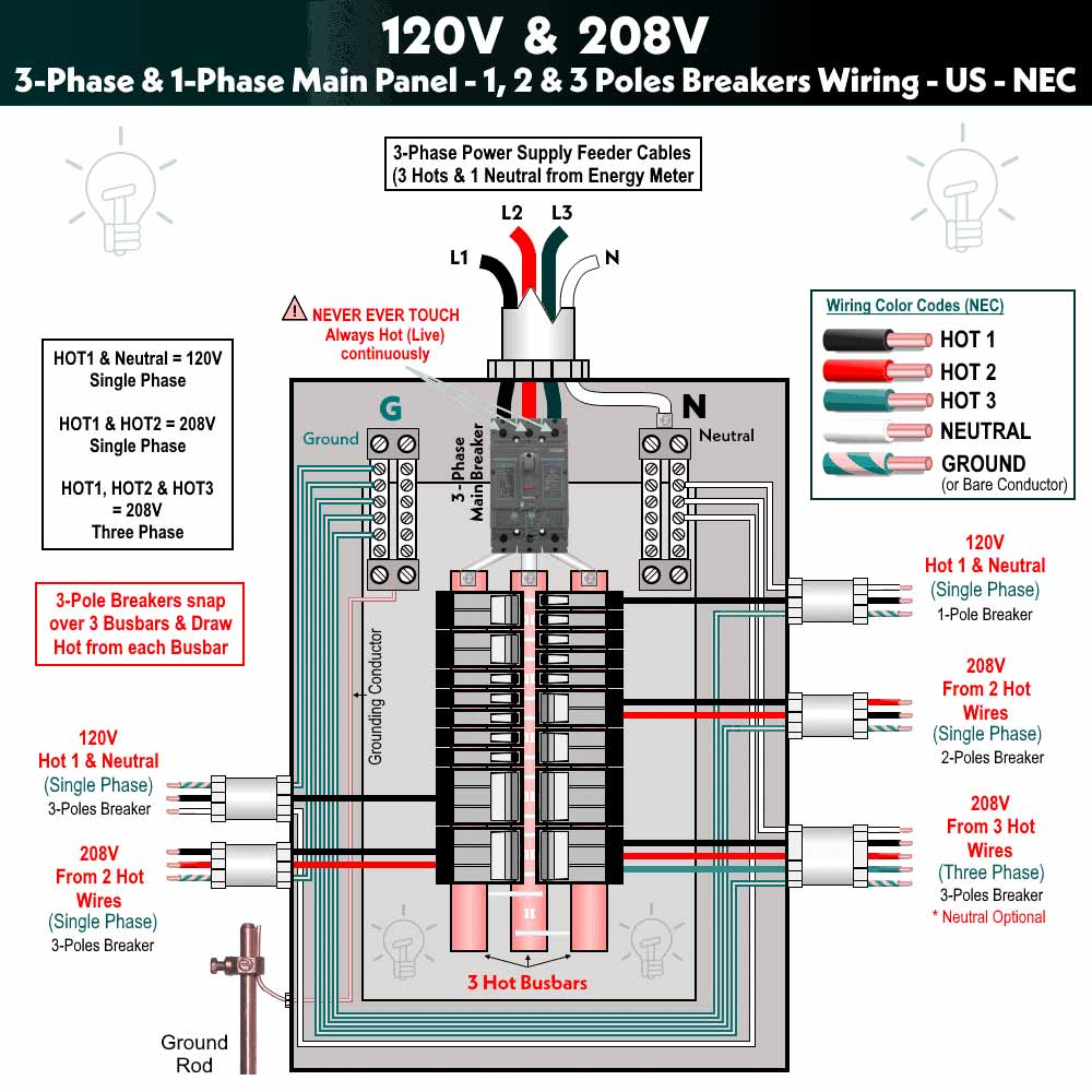
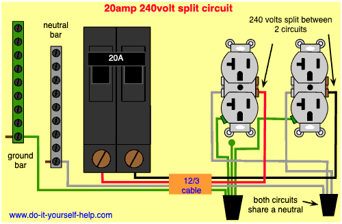
Reading a diagram of a 20amp house breaker requires familiarity with standardized schematic symbols, terminal designations, and line types representing physical conductors. Solid lines typically designate current-carrying hot and neutral conductors, while dashed or green lines indicate equipment grounding conductors. The diagram illustrates the main breaker feeding sub-panels or individual branch breakers, showing how the breaker clips onto the hot bus bar while the load wire terminates directly at the breaker load screw.
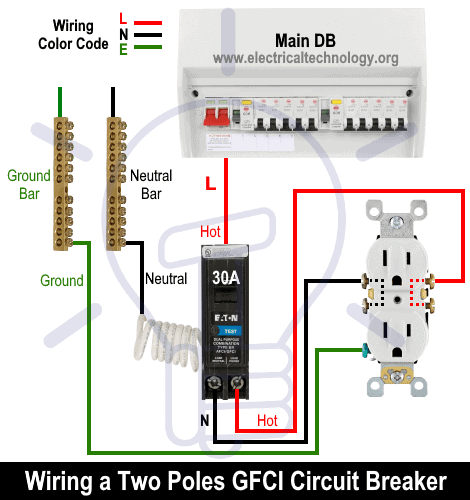
Key components visible on the schematic include the toggle switch (indicating ON, OFF, and tripped positions), the line terminal receiving power from the bus bar, and the load terminal securing the outgoing 12 AWG or 2.5 mm² cable. Advanced schematics may also incorporate Arc-Fault Circuit Interrupter (AFCI) or Ground-Fault Circuit Interrupter (GFCI) electronic modules built directly into modern 20-amp breakers. These specialized components feature internal sensing coils that monitor current balance and waveform signatures, requiring an additional pigtail neutral wire connected to the panel neutral bar.
Color coding varies significantly by geographic region and must be verified against local regulations before touching any hardware. In North America, typical 120V wiring utilizes black for hot, white for neutral, and bare copper or green for ground. In the UK and Europe under BS 7671, the live conductor is brown, the neutral is blue, and the protective earth is green-and-yellow striped. Australia and New Zealand utilize red or brown for active, black or light blue for neutral, and green-and-yellow for earth.
Common Problems and Troubleshooting Methods
Typical faults associated with 20-ampere circuits include nuisance tripping, loose terminal connections, degraded wire insulation, and permanent internal breaker failure due to repeated short-circuit events. Systematic diagnosis begins with visual inspections at both the service panel and the downstream receptacles, checking for discoloration, melted insulation, or signs of arcing. Technicians must always de-energize the panel and verify zero voltage using a calibrated multimeter before touching internal components.
When a 20-amp breaker trips repeatedly immediately upon resetting, the fault is generally a dead short or a ground fault on the circuit. Isolation testing requires disconnecting the load wire from the breaker terminal and measuring resistance between hot and neutral, as well as hot and ground, using an insulation resistance tester or standard multimeter. If continuity is detected between hot and neutral with all loads unplugged, a pinched or damaged cable exists somewhere in the run.
If the breaker trips intermittently under heavy load, the issue is often an overload condition where concurrent appliances draw more than 2400 watts (20 amps at 120 volts). Measuring actual running current with a clamp meter around the hot conductor while appliances operate will confirm whether the circuit is drawing excessive current. For further guidance on diagnosing complex residential issues, consult resources dedicated to Wiring Troubleshooting to refine isolation techniques.
Practical Tips and Safety Considerations
Working inside a residential electrical panel presents severe electrocution and arc-flash hazards that demand strict adherence to safety protocols and personal protective equipment usage. Mains-voltage systems must be completely de-energized, main breakers opened, and lockout/tagout procedures applied where applicable. Always verify zero energy state with a known-working, CAT-rated voltage tester directly at the breaker terminals before handling conductors.
A frequent mistake during DIY installation is failing to torque breaker terminal screws to the manufacturer’s precise specification, leading to high-resistance connections and dangerous localized heating. Torque screwdrivers should be utilized to ensure proper clamping force on both copper and aluminum conductors. Furthermore, never substitute a 20-ampere breaker onto a circuit wired with 14 AWG cable (which is strictly rated for 15 amperes), as this mismatch creates a severe fire hazard by allowing overloads before the wire can trigger protection.
Compliance with local electrical authorities—such as the NEC in the US, CEC in Canada, BS 7671 in the UK, or AS/NZS 3000 in Australia—is mandatory for all permanent wiring modifications. When local laws or project complexity exceed comfort levels, engage a licensed electrician to perform the installation or panel modification.
Conclusion
Mastering the layout and function of a high-capacity residential circuit ensures long-term electrical safety and operational reliability throughout the building. By correctly interpreting schematic symbols, respecting regional wire sizing rules, and executing methodical diagnostic procedures, technicians and homeowners can prevent dangerous electrical hazards. Proper installation and diligent maintenance safeguard both expensive appliances and the physical structure itself. For broader structural layout comprehension, reviewing Wiring Diagram Basics provides an essential foundation for tackling any residential or industrial electrical project.
Quick Wiring Specifications & Terminal Guide
| Component / Circuit | Standard Wire Gauge | Recommended Protection |
|---|---|---|
| Control & Trigger Signals | 18 – 20 AWG | 5A – 7.5A Inline Fuse |
| Standard Auxiliary Load | 14 – 16 AWG | 15A – 20A Circuit Breaker |
| Main Power Feed / Supply | 10 – 12 AWG | 30A – 40A Heavy-Duty Relay |
Images References