Introduction
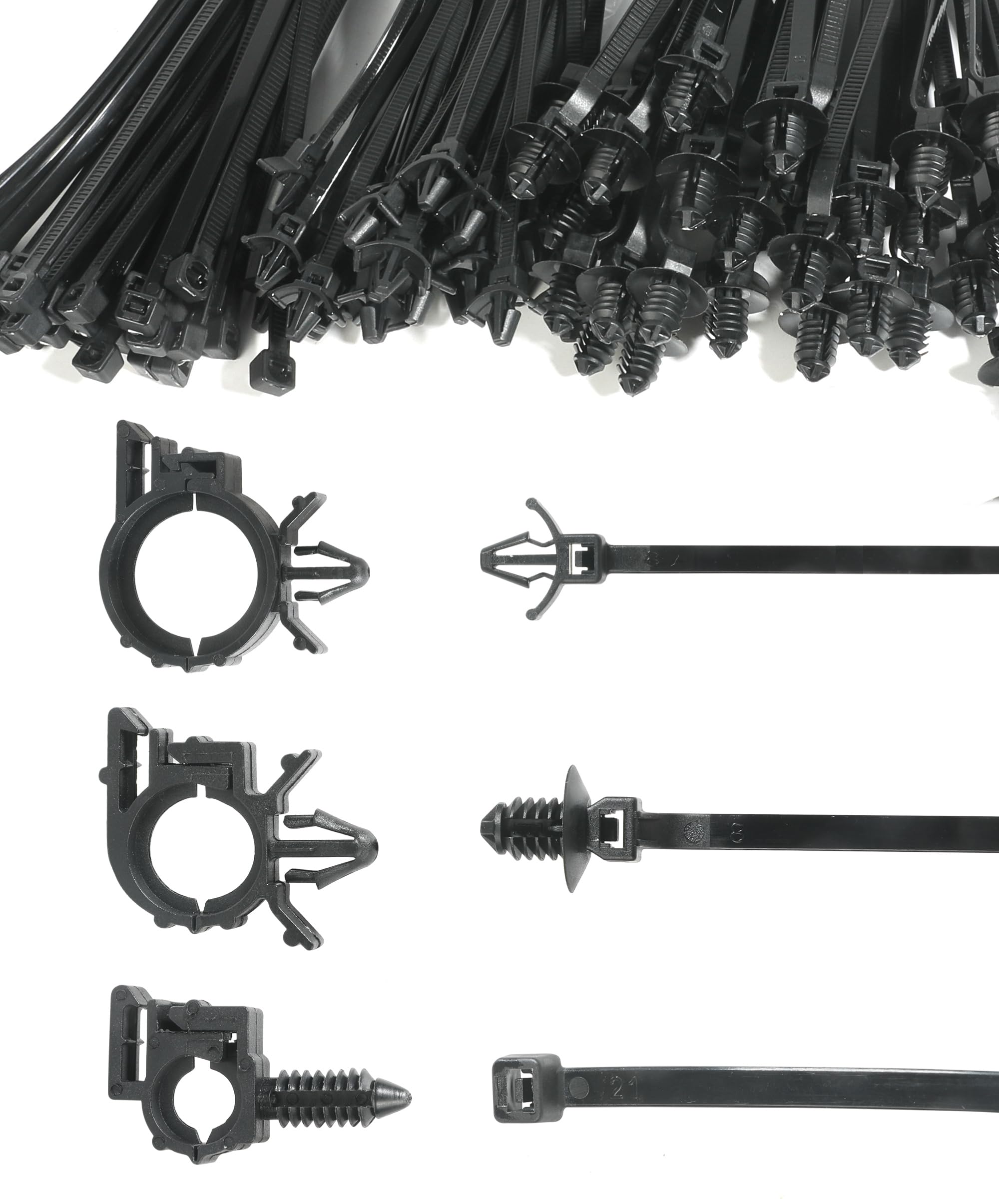
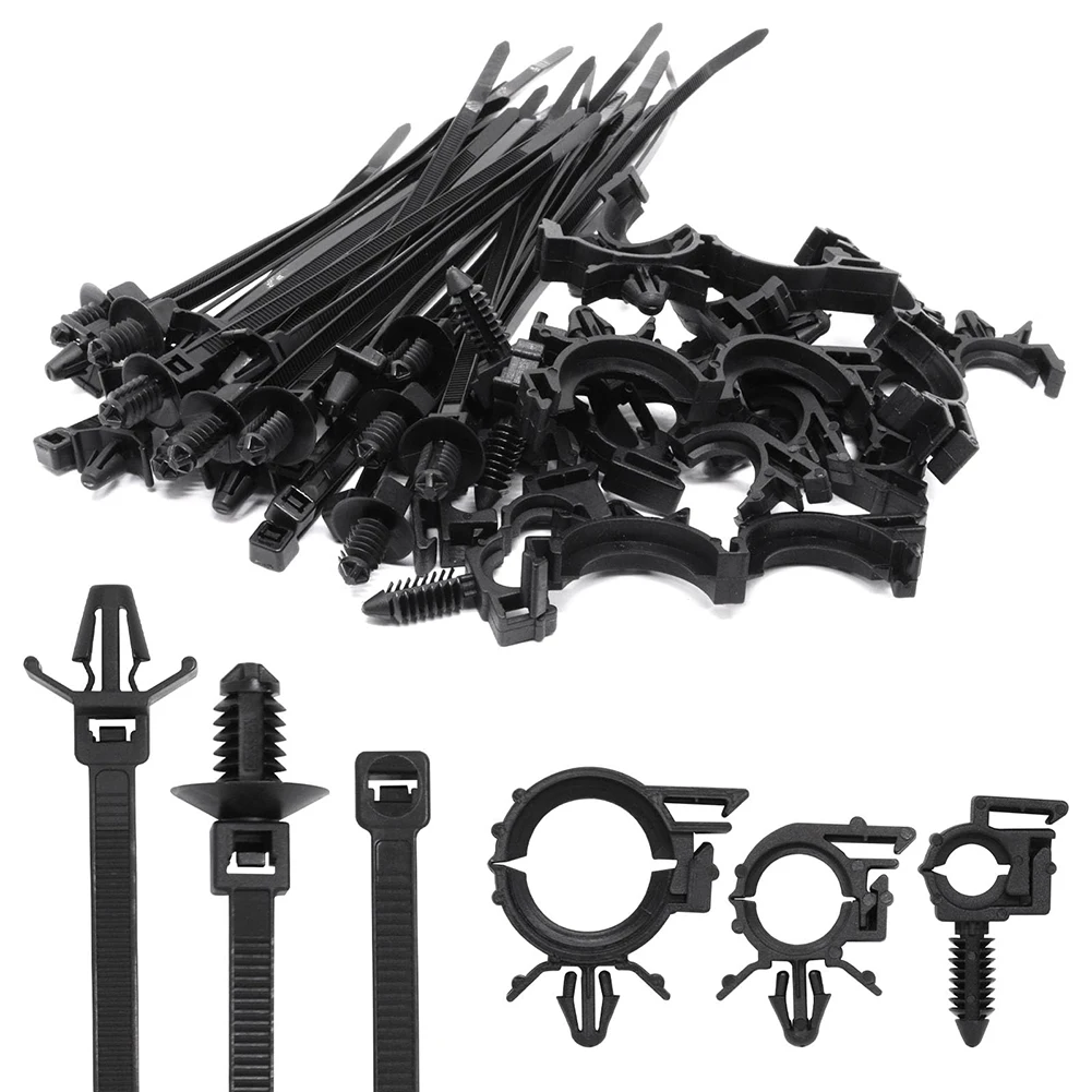
Automotive cable zip ties are specialized polymeric fasteners engineered to secure, route, and protect wire harnesses against mechanical vibration, thermal stress, and fluid exposure in 12V and 24V vehicle architectures. According to SAE J1128 automotive wiring standards, proper physical routing and restraint of primary wire harnesses prevent insulation abrasion that routinely causes intermittent shorts or catastrophic electrical faults. Within complex automotive electrical systems, these fasteners do far more than tidy engine bays; they establish strict geometric compliance with factory Vehicle Wiring Diagrams. Maintaining structural integrity across multi-branch circuits requires understanding how material composition, tensile strength, and environmental ratings intersect during systematic installation and field troubleshooting.
Wiring Technical Snapshot:
- Core Focus: Mechanical restraint and routing of 12V/24V automotive wire harnesses using engineered zip ties.
- Target Scope: Engine bays, chassis channels, body panels, and custom Relay and Component Wiring Diagrams installations.
- Key Recommendation: Always select UV-stabilized or heat-stabilized nylon grades and trim tails flush to eliminate sharp edges.
Core Principles and Detailed Overview
Automotive cable zip ties rely on high-tensile locking pawls and resilient polymer matrices—typically Heat-Stabilized Nylon 6/6 or impact-modified weather-resistant compounds—to maintain continuous clamping force under harsh operating conditions. When technicians analyze Wiring Troubleshooting logs, harness chafing against unshielded chassis sheet metal consistently emerges as a leading root cause for blown fuses and erratic sensor signals. Proper cable management mandates that main trunk lines follow factory routing paths explicitly marked on comprehensive General and Miscellaneous Wiring Diagrams. Securing bundles with correct spacing prevents resonant frequencies from fatiguing copper strands internally while safeguarding auxiliary circuits integrated into Audio and Entertainment Wiring Diagrams.
Key Specifications and Breakdown
| Circuit / Terminal | Standard Wire Color / Gauge | Operational Role & Safety Check |
|---|---|---|
| Primary 12V Battery Feed | Red / 8 AWG – 4 AWG | High-current main power distribution requiring heavy-duty, stainless-steel locking barb zip ties anchored securely away from moving exhaust components. |
| Chassis Ground Return | Black / 12 AWG – 10 AWG | Completes low-side current paths; verify continuity with a digital multimeter after securing bundles to structural frame members. |
| Engine Sensor Signal | Multi-Color Striped / 18 AWG – 22 AWG | Low-voltage data transmission vulnerable to electromagnetic interference; route and bundle cleanly away from high-tension ignition coils. |
Secure mechanical fastening and proper wire bundle routing are fundamental to preventing thermal overload and insulation breakdown in mobile electrical networks — National Fire Protection Association (NFPA)
Step-by-Step Practical Application and Guidelines
Executing a professional harness installation requires looping automotive cable zip ties loosely around the designated wire group before pulling them to the correct tension using a calibrated tensioning tool. Technicians must never over-tighten these fasteners, as excessive radial pressure crushes internal conductor insulation, compromises stranded copper flexibility, and invites internal short circuits. When transitioning harnesses from engine compartments to passenger cabins, secure the lines firmly to dedicated body studs or welded clips rather than pinching them against sharp panel edges. Following precise structural guidelines ensures that complex homebrew upgrades match the reliability standards outlined in professional Home Electrical Wiring Diagrams and secondary Appliance and Device Wiring applications.
Common Challenges and How to Avoid Them
Using standard indoor-grade nylon zip ties in high-temperature under-hood environments invariably leads to embrittlement, thermal cracking, and catastrophic bundle failure within months of service. Diagnostic specialists frequently encounter auxiliary lighting or aftermarket audio installations where poorly trimmed zip tie tails have severed adjacent thin-gauge sensor wires like those mapped in specialized Networking and Communication Wiring Diagrams. To mitigate these hazards, always verify operating temperature ranges, choose metal-barb ties for vibration-heavy chassis locations, and reference foundational Wiring Diagram Basics to confirm that harness routing respects minimum bend radii and heat source clearances.
💬 Frequently Asked Questions
Explore More Wiring Diagrams and Schematics on ReadWires
Mastering mechanical wire restraint and electrical safety protocols empowers technicians to build reliable, professional-grade automotive circuits that withstand severe environmental conditions. Expand diagnostic proficiency by reviewing comprehensive technical resources, schematics, and schematics interpretation guides available directly through ReadWires.com.
Visual Reference Gallery