Introduction
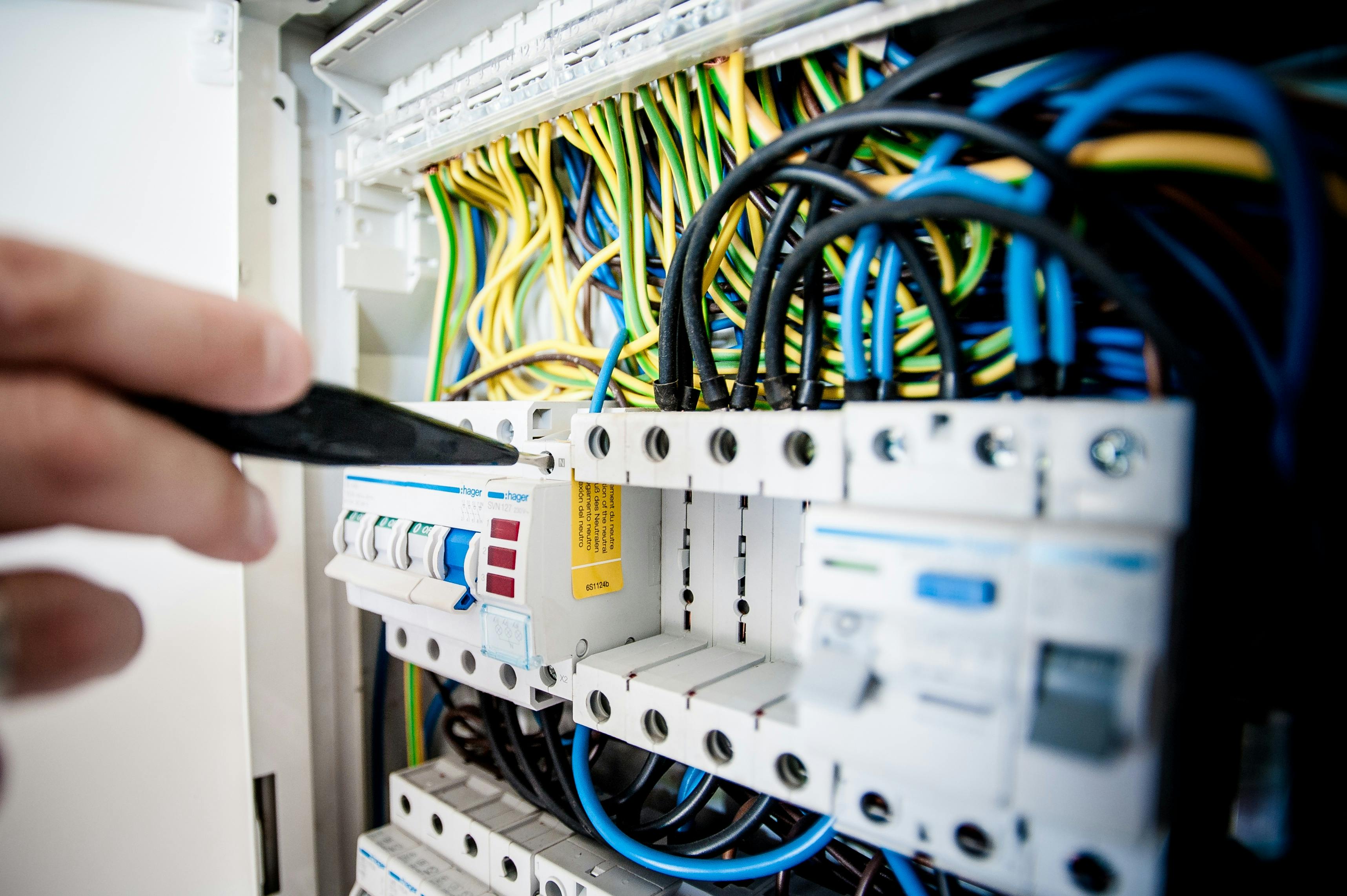
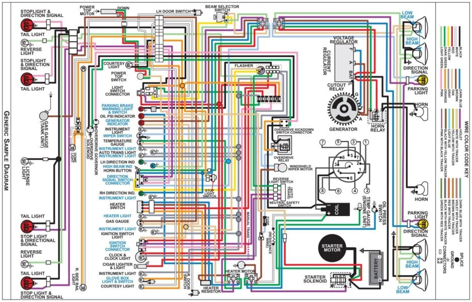
Wiring general encompasses the foundational installation, routing, protection, and systematic diagnosis of low-voltage automotive and high-voltage residential electrical circuits. According to SAE J1128 automotive wiring standards, proper conductor selection and insulation integrity are mandatory to prevent voltage drop, thermal overload, and catastrophic short circuits in mobile and stationary power distribution networks. Mastering circuit theory requires navigating both direct current (12V/24V) transport principles and alternating current structural grids safely. Technicians must understand schematics found across Wiring Diagram Basics to interpret component locations, terminal designations, and harness routing paths effectively. Modern diagnostic workflows demand precision, adherence to standardized color-coding, and methodical voltage drop testing across every splice, fuse, and connector.
Wiring Technical Snapshot:
- Core Focus: Safe management, installation, and systematic troubleshooting of electrical conductor systems.
- Target Scope: 12V/24V automotive architectures and residential AC power grids.
- Key Recommendation: Always verify continuity, measure voltage drop, and consult official schematics before modifying circuits.
Core Principles and Detailed Overview
Comprehensive circuit comprehension relies on Ohm’s Law, Kirchhoff’s circuit laws, and precise schematic interpretation across diverse physical platforms. Technicians must differentiate between automotive chassis ground returns and isolated home neutral-ground bonding configurations to prevent erratic equipment behavior and safety hazards. Navigating complex networks becomes streamlined when studying specialized layouts within General and Miscellaneous Wiring Diagrams. Electrical resistance, current draw, and source voltage dictate conductor gauge selection according to ampacity charts, ensuring copper or aluminum wires never exceed safe thermal thresholds during continuous heavy loads.
Key Specifications and Breakdown
| Circuit / Terminal | Standard Wire Color / Gauge | Operational Role & Safety Check |
|---|---|---|
| Automotive Battery Positive | Red / 4 AWG to 8 AWG | Transfers unswitched main power from alternator/battery; verify clean terminal torque and zero corrosion. |
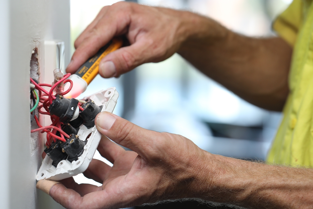
| Residential Hot Conductor | Black / 12 AWG (15A-20A) | Carries high-voltage AC load current; test with a non-contact voltage detector and multimeter before servicing. |
| Chassis / Equipment Ground | Bare Copper or Green / 10 AWG | Provides safe fault-current return path; check continuity to frame/earth using resistance mode (< 0.5 ohms). |
Proper circuit protection sizing requires matching the fuse rating precisely to the conductor’s maximum ampacity to prevent insulation melting and electrical fires. — National Fire Protection Association (NFPA)
Step-by-Step Practical Application and Guidelines
Executing professional electrical modifications or repairs demands a strict sequential methodology from initial power isolation to final verification testing. First, disconnect the negative battery terminal on automotive systems or trip the designated circuit breaker on home distribution panels to establish a zero-energy state. Second, strip wire insulation cleanly using calibrated strippers to avoid nicking conductor strands, and utilize heat-shrink butt connectors or soldered joints sealed with adhesive-lined tubing. Third, reference schematics provided in Home Electrical Wiring Diagrams to verify correct terminal assignments before restoring power. Finally, perform a dynamic voltage drop test under actual load conditions to confirm resistance remains within acceptable operational tolerances.
Common Challenges and How to Avoid Them
Intermittent electrical faults, high-resistance corrosion, and improper wire sizing remain the most frequent challenges encountered during advanced diagnostic evaluations. Technicians frequently misdiagnose failing components when the root cause stems from oxidized ground points or stretched pin tension inside multi-pin connectors. Utilizing back-probing techniques instead of piercing insulation prevents moisture ingress and subsequent copper rot within vehicle harnesses. Reference specialized fault-finding procedures through Wiring Troubleshooting to systematically isolate open circuits, shorts to ground, and parasitic draws without damaging sensitive electronic control modules.
💬 Frequently Asked Questions
Explore More Wiring Diagrams and Schematics on ReadWires
Mastering automotive and residential electrical systems requires continuous reference to accurate, manufacturer-grade documentation and schematics. Practitioners can expand their technical expertise by browsing the extensive diagnostic library hosted at ReadWires.com. Utilizing proper schematics ensures every repair meets strict industry standards for safety, longevity, and optimal performance across all electrical domains.
Wiring Diagram Schematics & Details