
Introduction
An electrical wiring diagram book pdf serves as a critical technical reference manual providing schematics, pinout charts, and circuit path layouts for automotive 12V/24V systems and residential electrical infrastructures. According to SAE International, standardized automotive wiring guidelines require precise schematic symbols and wire color coding to ensure reliable circuit diagnosis and prevent catastrophic electrical failures during maintenance. Accessing these documents digitally allows technicians and DIY mechanics to zoom into complex harness junctions, trace component loops, and execute accurate Wiring Troubleshooting procedures on mobile devices or diagnostic laptops.
Wiring Technical Snapshot:
- Core Focus: Digital schematics for interpreting automotive and home electrical pathways.
- Target Scope: 12V/24V automotive harnesses, heavy equipment circuits, and residential distribution networks.
- Key Recommendation: Always cross-reference PDF terminal identifiers with physical multimeter continuity tests before bypassing circuits.
Core Principles and Detailed Overview
Digital schematics found within an electrical wiring diagram book pdf translate complex physical wire bundles into readable logical flows utilizing standardized symbols for relays, switches, grounds, and power distribution modules. Mastering Wiring Diagram Basics is essential for interpreting abbreviations like G101 (Ground point 101) or identifying fused links within Relay and Component Wiring Diagrams. Technicians rely on these portable documents to navigate intricate Vehicle Wiring Diagrams that map out CAN bus communication lines, powertrain control modules, and accessory networks. Whether evaluating low-voltage data transmission or high-amperage residential grids documented in Home Electrical Wiring Diagrams, possessing a clear reference manual eliminates guesswork and ensures adherence to circuit load limits.
Key Specifications and Breakdown
| Circuit / Terminal | Standard Wire Color / Gauge | Operational Role & Safety Check |
|---|---|---|
| Automotive Battery Positive (B+) | Red / 10 AWG to 4 AWG | Delivers continuous unswitched power; verify voltage drop under load using a digital multimeter. |
| Chassis Ground (GND) | Black or Bare Copper / 12 AWG | Completes the electrical return path; test for excessive resistance below 0.5 ohms against chassis steel. |
| Switched Ignition Feed | Yellow or Orange / 14 AWG | Energizes accessories upon key turn; inspect inline fuses for thermal fatigue or corrosion. |
National Electrical Safety Standard Compliance — Electrical Safety Foundation International (ESFI)
Wiring Diagram Schematics & Details


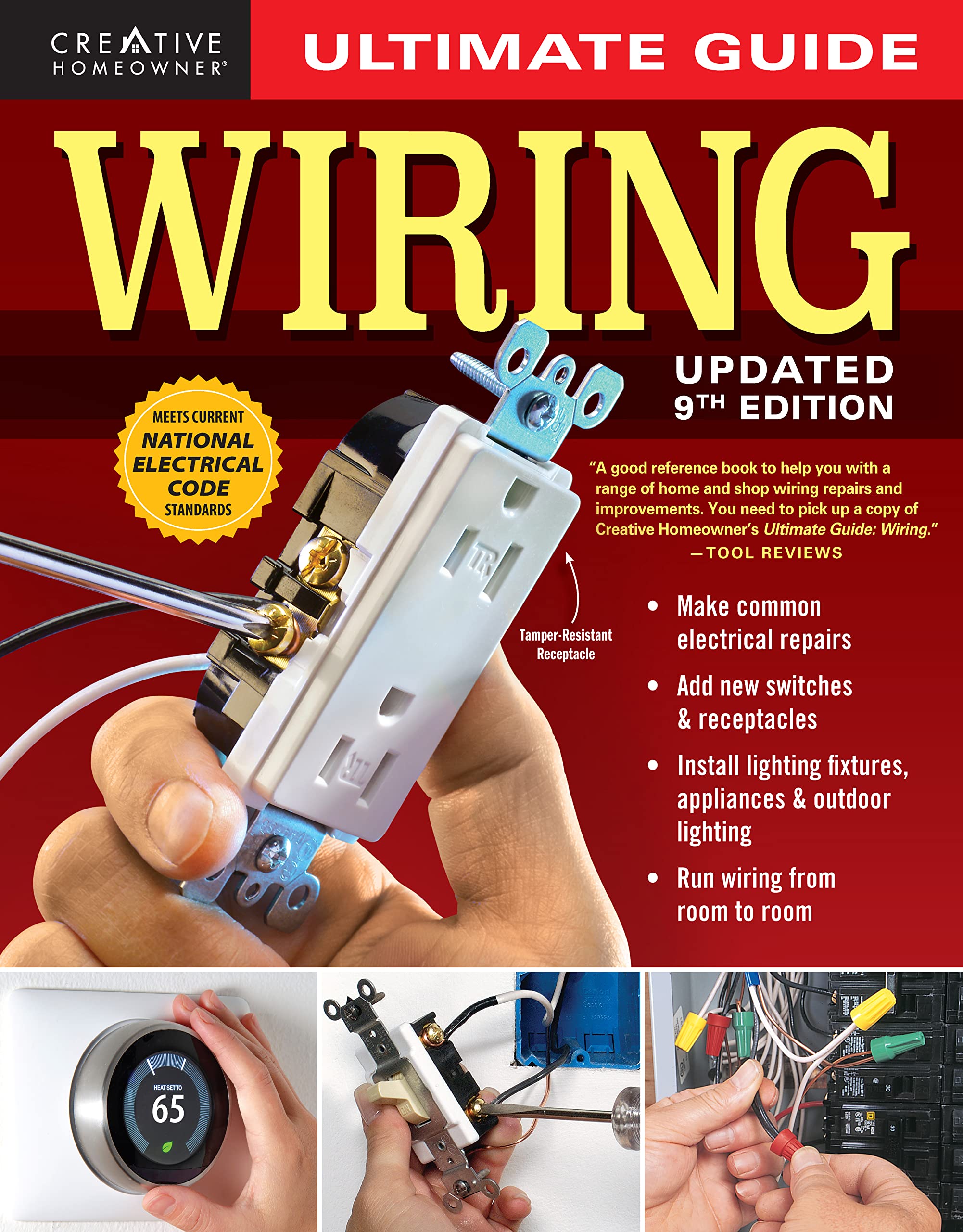

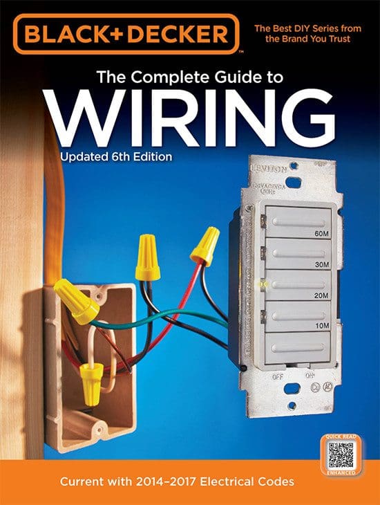


Step-by-Step Practical Application and Guidelines
Executing a successful diagnostic workflow using an electrical wiring diagram book pdf requires systematically isolating the suspected subsystem, locating the corresponding power feed, and tracing the ground return path. Begin


