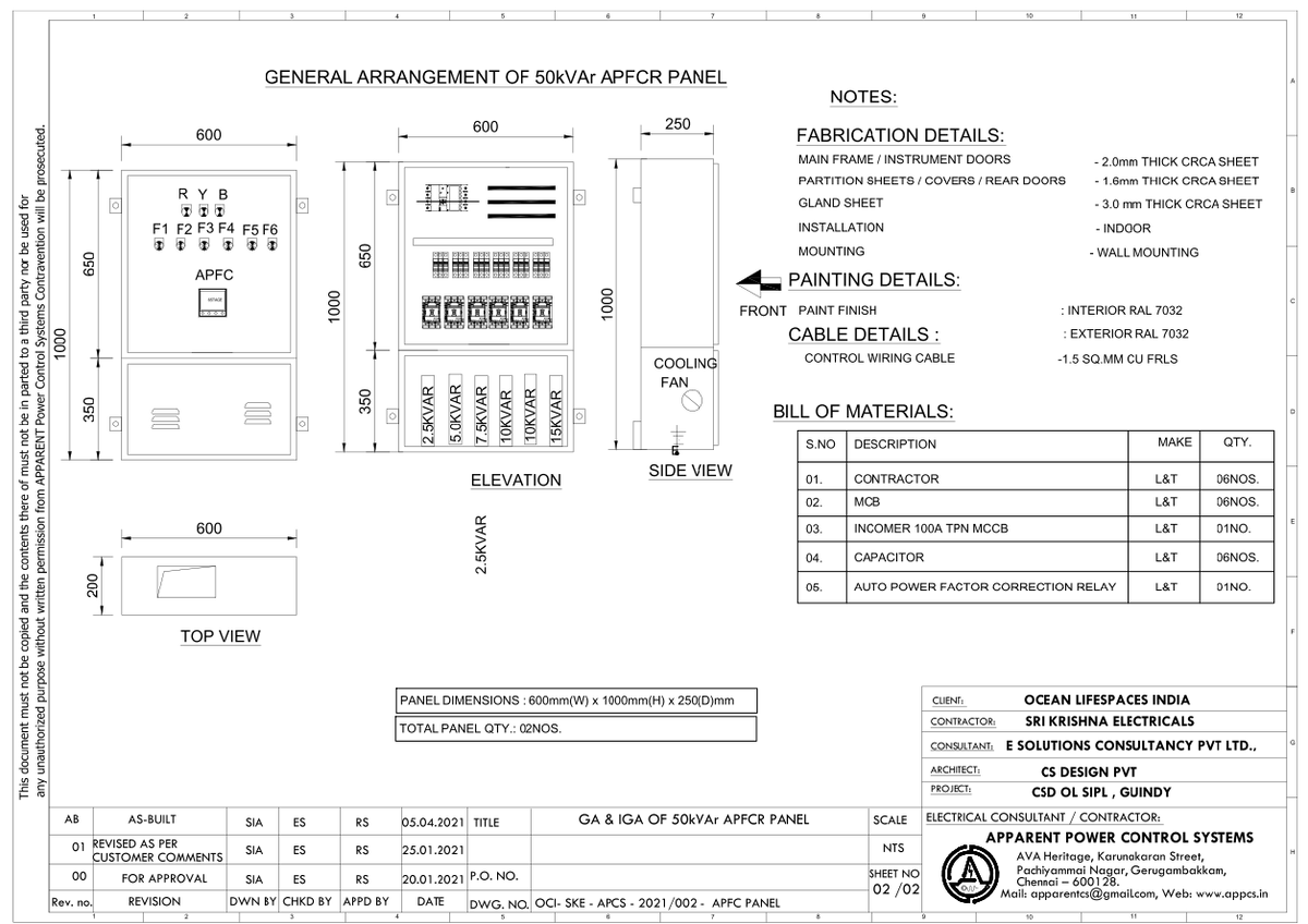
Introduction
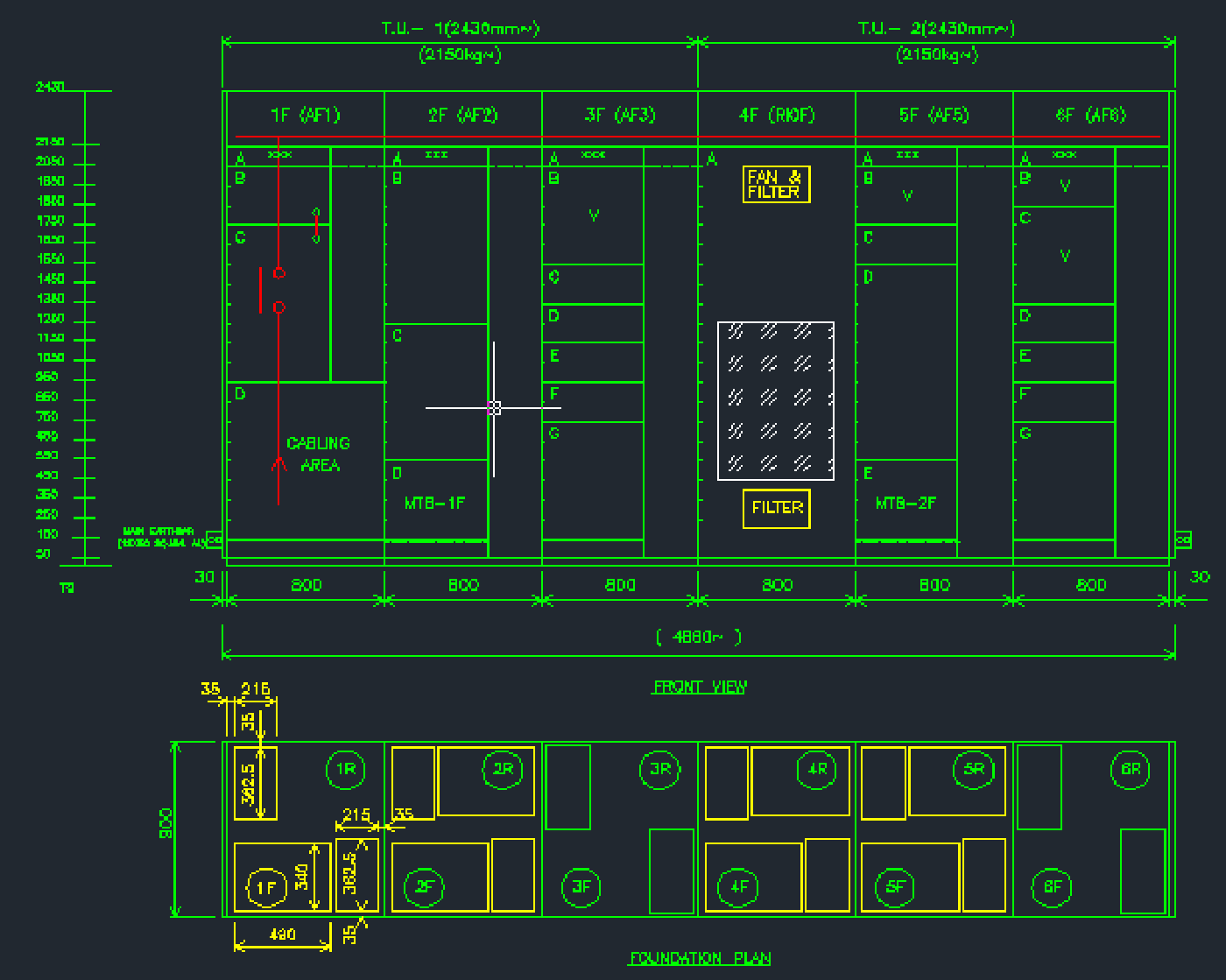
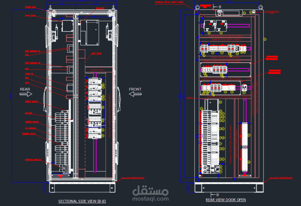
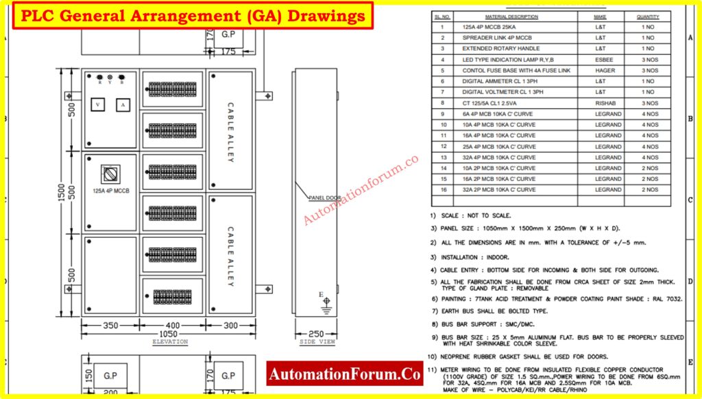
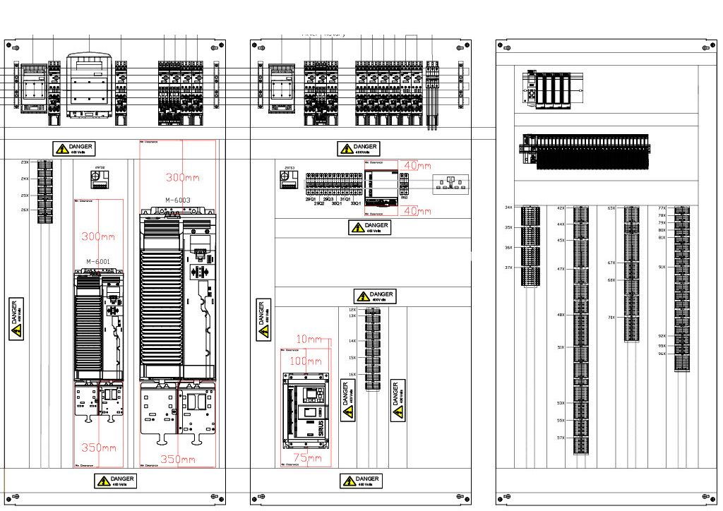
A general arrangement panel serves as the master spatial layout map that dictates the physical placement, termination points, and routing pathways of electrical hardware within a 12V/24V automotive chassis or residential distribution enclosure. According to SAE J1128 automotive wiring standards, proper physical documentation and layout organization prevent critical circuit cross-talk, mechanical chafing, and thermal overload during high-current operations. Grasping this blueprint is essential for mastering Wiring Diagram Basics before executing complex multi-system integration or repairs.
Wiring Technical Snapshot:
- Core Focus: Spatial mapping and hardware layout for electrical distribution enclosures.
- Target Scope: Automotive 12V/24V chassis builds and complex home electrical panels.
- Key Recommendation: Always cross-reference physical layout drawings with schematic line diagrams prior to terminal termination.
Core Principles and Detailed Overview
A general arrangement panel defines the exact physical locations of relays, breakers, terminal strips, busbars, and cable entry glands to maximize maintenance accessibility and minimize electromagnetic interference. Direct spatial planning ensures that high-amperage power leads remain physically separated from low-voltage data lines, safeguarding sensitive control modules from inductive spikes. Technicians rely heavily on this drawing type when untangling legacy harnesses or mapping custom Home Electrical Wiring Diagrams where spatial constraints dictate component placement. By establishing a rigid physical framework, this documentation prevents guesswork, reduces installation errors, and accelerates systematic Wiring Troubleshooting when intermittent faults occur.
Key Specifications and Breakdown
| Circuit / Terminal | Standard Wire Color / Gauge | Operational Role & Safety Check |
|---|---|---|
| Main Power Feed | Red / 2 AWG (Automotive) or 4 AWG (Residential) | Carries primary battery or mains feed; verify zero voltage drop under load using a digital multimeter. |
| Chassis / Earth Ground | Black or Bare Copper / 4 AWG | Provides low-resistance return path; inspect ring terminal crimp and ensure bare metal frame contact. |
| Switched Relay Trigger | Yellow or Blue / 16 AWG | Delivers low-current control signal; check continuity and trigger voltage against manufacturer parameters. |
Proper physical separation of high-voltage and low-voltage wiring within an enclosure is mandatory to prevent dangerous inductive coupling and ensure compliance with recognized electrical safety frameworks. — National Fire Protection Association (NFPA)
Step-by-Step Practical Application and Guidelines
Implementing a general arrangement panel requires a methodical process starting with surface layout planning, dry-fitting hardware components, and verifying terminal clearance distances. Technicians must first secure the backing plate inside the enclosure, mounting heavy items like busbars and master disconnect relays near structural anchor points. Next, secure wire management raceways to channel conductors away from sharp sheet-metal edges and moving mechanical linkages. Before energizing the system, perform a comprehensive continuity test across every terminal block to isolate short circuits, referencing specialized Relay and Component Wiring Diagrams to confirm pinout accuracy.
Common Challenges and How to Avoid Them
Overcrowded terminal enclosures and poor wire management represent the most frequent causes of thermal buildup, high-resistance connections, and diagnostic failure in custom electrical builds. Technicians frequently commit the error of running sensitive signal wires parallel to high-current alternator leads, introducing severe electromagnetic noise into audio and sensor networks. Mitigate these hazards by adhering strictly to designated raceway channels, applying heat-shrink insulation to all crimp terminals, and leaving adequate service loops for future maintenance modifications. Careful adherence to structured layout practices ensures long-term system reliability across diverse Vehicle Wiring Diagrams and mobile power setups.
💬 Frequently Asked Questions
Explore More Wiring Diagrams and Schematics on ReadWires
Mastering physical layout principles and electrical schematics is essential for safe, reliable circuit modification across automotive, marine, and residential applications. Explore the comprehensive reference library available at ReadWires.com to access detailed documentation, including specialized Audio and Entertainment Wiring Diagrams and General and Miscellaneous Wiring Diagrams tailored for every diagnostic scenario.
Visual Reference Gallery