Introduction
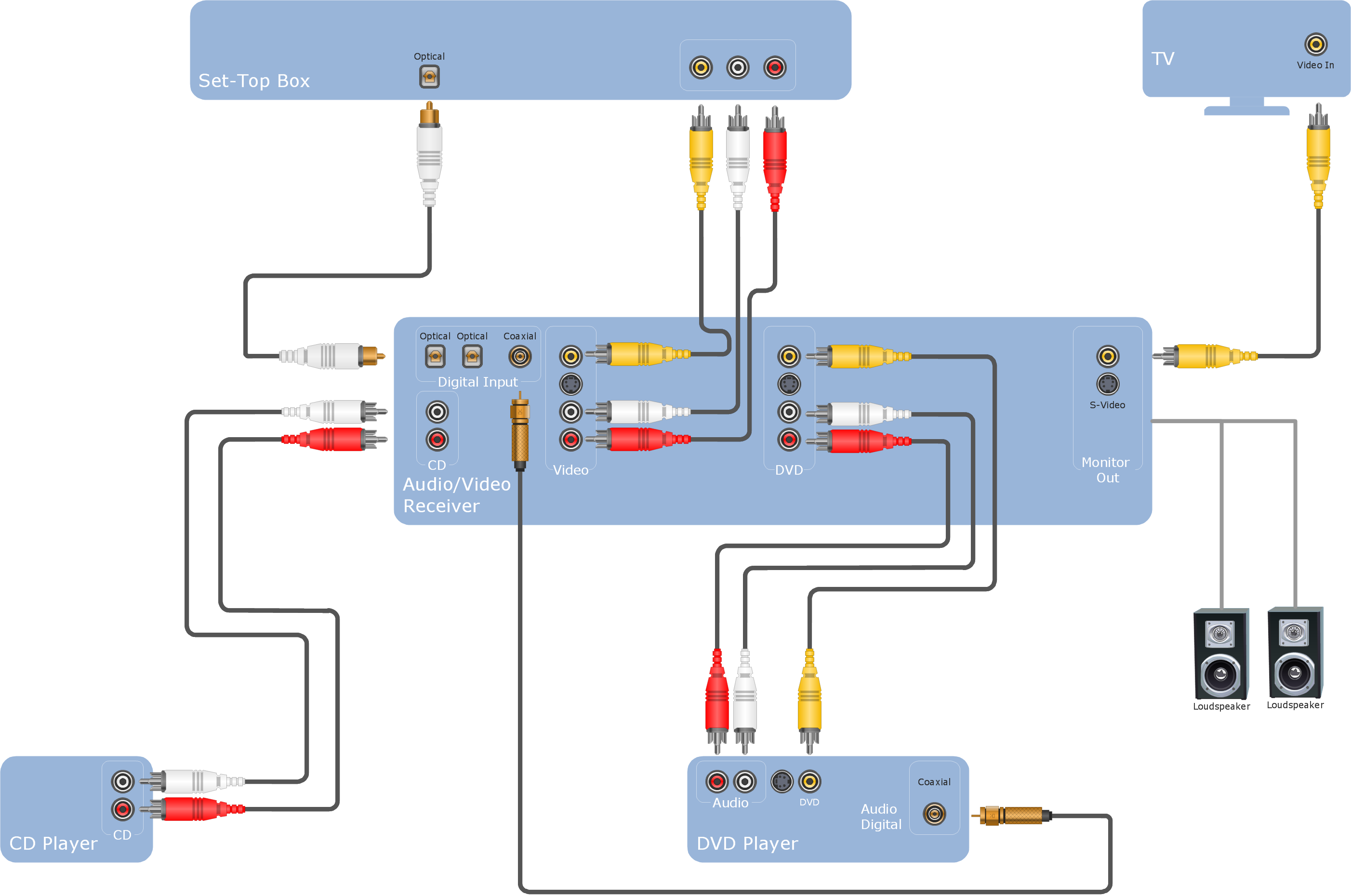
Wiring audio involves systematically routing, terminating, and shielding low-voltage signal cables and high-current power lines to ensure distortion-free sound reproduction and complete circuit integrity. According to SAE J1128 automotive wiring standards, selecting the proper copper conductor size and insulation rating is mandatory to prevent voltage drop and thermal overload in 12V and 24V electrical architectures. Mastering this technical discipline requires adherence to schematic layouts, precise terminal crimping, and meticulous ground distribution. Professionals rely on systematic methodologies found within Audio and Entertainment Wiring Diagrams to map complex factory and aftermarket system integrations.
Wiring Technical Snapshot:
- Core Focus: Integration of power, ground, remote turn-on, and speaker-level or line-level signal paths.
- Target Scope: Automotive 12V/24V cabins, marine audio setups, and auxiliary home electronics.
- Key Recommendation: Physically separate low-level RCA signal lines from high-current power cables to eliminate electromagnetic interference (EMI).
Core Principles and Detailed Overview
Understanding the underlying physics of electrical resistance, impedance matching, and ground loops dictates the success of any wiring audio installation. Direct answer: Every audio circuit operates through a closed-loop topology where power delivery, signal transfer, and transducer resistance must remain perfectly balanced to avoid clipping and amplifier thermal protection events. In 12V automotive environments, calculating total amplifier current draw using Ohm’s Law determines the necessary power wire gauge (AWG). When technicians review Vehicle Wiring Diagrams, identifying factory-amplified bypass loops and data-bus turn-on triggers prevents catastrophic module damage. Furthermore, shielding balanced differential lines protects sensitive analog signals from alternator whine and injector pulse noise.
Key Specifications and Breakdown
| Circuit / Terminal | Standard Wire Color / Gauge | Operational Role & Safety Check |
|---|---|---|
| Constant 12V Power (B+) | Yellow / 4 AWG to 8 AWG | Delivers primary energy from the battery; verify inline fuse is within 18 inches of the terminal. |
| Remote Turn-On (REM) | Blue / White Stripe / 18 AWG | Sends a 12V trigger signal from the head unit to activate amplifiers; check voltage output using a digital multimeter. |
| Speaker Output Channels | Green, Purple, White, Grey / 14-16 AWG | Transfers amplified audio AC signals to voice coils; check impedance values using an ohmmeter to prevent short circuits. |
Proper circuit protection and overcurrent sizing are critical; fuses protect the wire harness from thermal failure and fire hazards, not the connected equipment. — National Fire Protection Association (NFPA)
Step-by-Step Practical Application and Guidelines
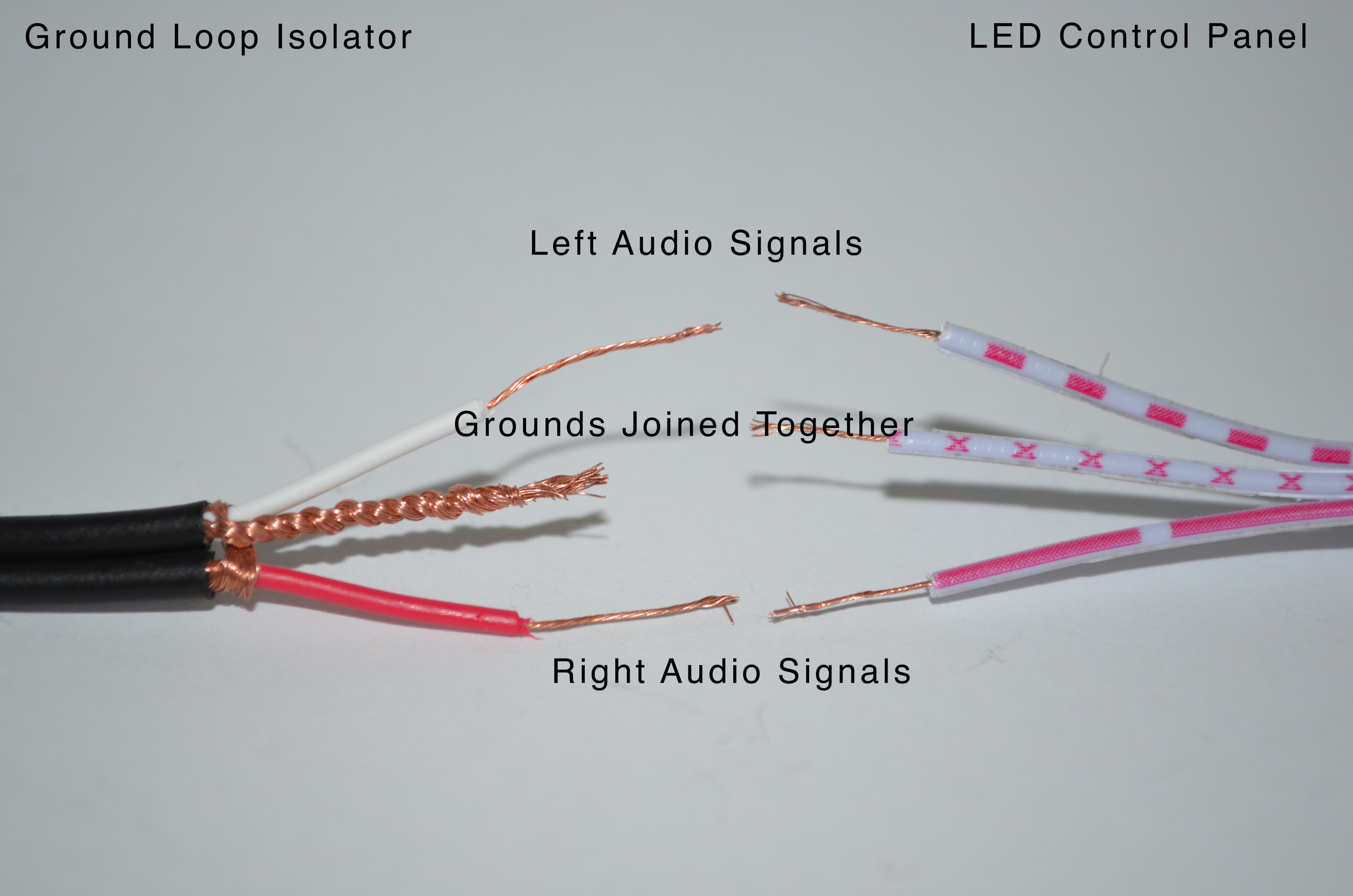
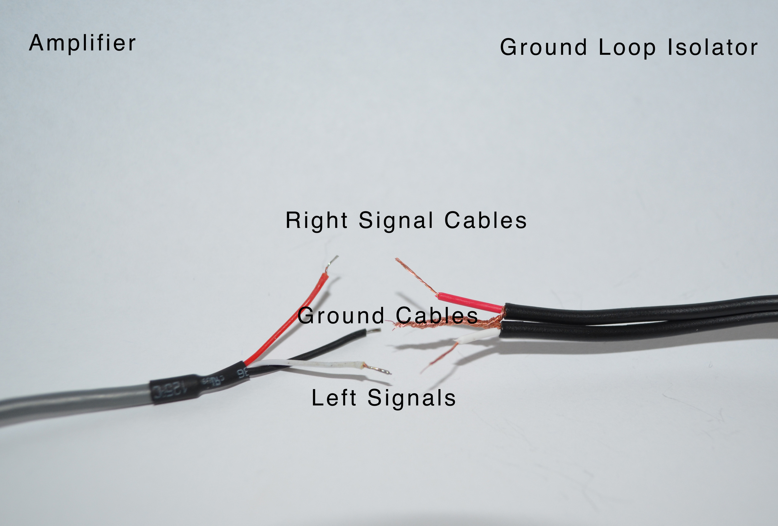
Executing a clean installation demands a methodical, step-by-step approach to wire routing, termination, and system testing. Direct answer: Begin by disconnecting the negative battery terminal, mapping out physical pathways away from factory computer harnesses, and securing all conductors with insulated P-clamps or nylon zip ties. Strip wire insulation cleanly using a calibrated mechanical stripper, avoiding nicked strands that introduce high-resistance bottlenecks. Crimp marine-grade heat-shrink terminals securely, apply heat with a dual-temperature heat gun to seal out moisture, and anchor the main ground wire to bare, sanded chassis metal using a star washer. Reviewing Wiring Troubleshooting procedures before initial power-up ensures shorted speaker leads or improper ground offsets are detected prior to amplifier activation.
Common Challenges and How to Avoid Them
Identifying common installation pitfalls prevents persistent audio distortion, intermittent signal loss, and equipment failure. Direct answer: Ground loops and alternator whine are the most frequent challenges, caused almost exclusively by high-resistance chassis ground points or running RCA signal cables parallel to high-amperage power leads. Technicians must correct these issues by relocating grounds to a single, centralized bare-metal chassis location and ensuring physical separation between power and signal wiring. Additionally, verifying speaker phase consistency across all channels prevents destructive acoustic cancellation and weak low-frequency response. Consulting references in Wiring Diagram Basics helps clarify color-coding ambiguities and factory polarity markings.
💬 Frequently Asked Questions
Explore More Wiring Diagrams and Schematics on ReadWires
Mastering complex electrical systems demands accurate, up-to-date schematics and diagnostic guides for every project phase. Whether servicing mobile entertainment setups or industrial control panels, having access to precise documentation prevents costly errors. Explore thousands of validated schematics and reference guides by visiting the main library at ReadWires.com to elevate every electrical installation.
Wiring Diagram Schematics & Details