Introduction
A headlamp wiring diagram for low beam and high beam serves as the visual roadmap for automotive illumination circuits, detailing the electrical path from the battery and switch to the dual-filament bulbs or modern solid-state modules. Mastering this schematic layout matters because proper night visibility relies entirely on uninterrupted circuit integrity, correct voltage delivery, and reliable switching between high and low intensities. These diagrams are used extensively across passenger vehicles, commercial trucks, and specialized transport equipment during restoration, custom upgrades, and electrical fault diagnostics. Understanding the underlying circuitry improves diagnostic accuracy, prevents costly component damage, and ensures safe operation on public roadways in the US, UK, Canada, and Australia.
💡 Technical Key Takeaways:
- Core Focus: Diagnostic schematic and terminal connection layout for Headlamp Wiring Diagram For Low Beam And High Beam.
- Target Scope: Field technicians, automotive DIYers, and residential/commercial electricians.
- Safety Rule: Always disconnect the primary power source/battery terminal and verify zero voltage with a multimeter before touching wires.
Core Concepts and Wiring Fundamentals
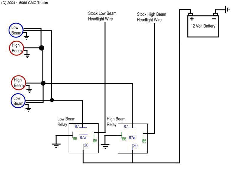
Automotive lighting circuits operate on a direct current (DC) system, typically utilizing 12-volt configurations in passenger vehicles and 24-volt setups in heavy commercial applications. Power originates at the battery or alternator, flows through a main fuse panel, and is regulated by cabin-mounted switches or multifunction steering column stalks. Because modern headlamps draw substantial electrical current, manufacturers frequently incorporate automotive relays—electrically operated switches that allow a low-current control circuit to manage a high-current load circuit—to protect delicate dashboard switches from thermal degradation.
The circuit relies on three main legs: power feed, load, and ground. The power feed delivers electrical potential from the source to the control device, while the load path routes current through the headlamp filaments or light-emitting diode (LED) drivers. Grounding completes the loop, returning current back to the vehicle chassis and ultimately to the negative battery terminal. A poor chassis ground is frequently the hidden culprit behind dim, flickering, or completely inoperative headlamps, illustrating why physical connection points require as much attention as insulated copper conductors.
[Vehicle lighting failures, including headlamp outages, represent a significant percentage of roadside safety infractions and are governed by regional equipment standards such as SAE J579 in North America and UNEP/ECE regulations internationally.] — Society of Automotive Engineers (SAE)
Diagram Explanation and Key Components
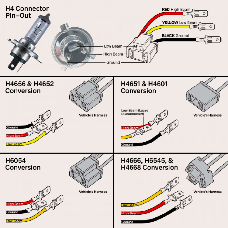
Reading a headlamp wiring diagram for low beam and high beam requires understanding standardized electrical symbols, wire color codes, and pin designations. Schematics typically use standard geometric symbols to represent fuses, SPDT (Single Pole Double Throw) relays, multi-pin connectors, and dual-filament bulbs like the H4 or 9003 types. Each line on the diagram represents an insulated conductor, frequently labeled with an alpha-numeric code indicating wire gauge, circuit function, and insulation color. In North American vehicles governed by SAE practices, color coding often follows standardized conventions, whereas European and UK diagrams referenced against BS or ISO standards may utilize numerical terminal designations like 56a for high beams and 56b for low beams.
The schematic maps the flow from the master lighting switch to the dimmer switch, which directs voltage exclusively to either the low-beam circuit or the high-beam circuit. Dual-filament bulbs contain two independent internal resistance paths enclosed in a single envelope; energizing one filament illuminates the low-beam pattern, while switching activates the second filament positioned to project a higher, farther-reaching light cone. For deeper insight into how auxiliary electrical hardware integrates into automotive layouts, review Vehicle Wiring Diagrams and specialized schematics found within Relay and Component Wiring Diagrams.
Common Problems and Troubleshooting Methods
Systematic diagnostic procedures transform frustrating electrical mysteries into straightforward repairs by isolating faults through logical measurement rather than guesswork. Typical failures in headlamp systems include blown fuses caused by short circuits, oxidized relay contacts preventing power transfer, burnt-out bulb filaments, and corroded chassis ground locations. When diagnosing an inoperative low-beam or high-beam circuit, a technician or DIY enthusiast should begin by verifying battery voltage, inspecting the relevant fuse, and testing for power at the bulb connector using a digital multimeter or a high-impedance test light.
If voltage is present at the connector but the bulb remains dark, the ground path or the bulb itself requires inspection. Conversely, if no voltage reaches the socket during switch activation, tracing the circuit backward through the wiring harness toward the relay and dashboard switch reveals the exact point of failure. Field experience shows that aftermarket high-wattage bulbs frequently overload factory wiring harnesses, causing premature relay failure or melted connector housings. Technicians seeking broader methodological approaches to electrical faults can consult strategies detailed under Wiring Troubleshooting.
Practical Tips and Safety Considerations
Working with automotive electrical systems demands strict adherence to safety protocols, particularly regarding high-current circuits and halogen bulb handling. Always disconnect the negative battery cable before cutting, splicing, or replacing major wiring harness components to prevent accidental short circuits, component damage, or personal injury. When handling quartz-halogen bulbs, technicians must avoid touching the glass envelope with bare fingers; oils left behind create hot spots on the quartz surface that cause premature bulb failure or shattering.
Wire sizing and insulation quality remain paramount when repairing or modifying headlamp circuits. Utilizing undersized wire gauges increases circuit resistance, generating excessive heat and potential fire hazards. Replacement conductors must match or exceed the original equipment manufacturer (OEM) specifications, and all splices must be sealed with adhesive-lined heat shrink tubing to prevent moisture ingress and green-rot corrosion. For additional guidance on reading foundational schematics before tackling complex vehicle harnesses, explore Wiring Diagram Basics.
Conclusion
Comprehending a headlamp wiring diagram for low beam and high beam bridges the gap between mechanical frustration and confident electrical repair. By recognizing standard schematic symbols, understanding the interplay between relays, switches, and grounds, and applying methodical diagnostic steps, technicians and DIY mechanics can accurately resolve complex lighting faults. Prioritizing correct wire gauges, secure grounding, and strict safety precautions ensures that lighting modifications and repairs remain reliable, legal, and safe for all road users.
Quick Wiring Specifications & Terminal Guide
| Component / Circuit | Standard Wire Gauge | Recommended Protection |
|---|---|---|
| Control & Trigger Signals | 18 – 20 AWG | 5A – 7.5A Inline Fuse |
| Standard Auxiliary Load | 14 – 16 AWG | 15A – 20A Circuit Breaker |
| Main Power Feed / Supply | 10 – 12 AWG | 30A – 40A Heavy-Duty Relay |
Images References