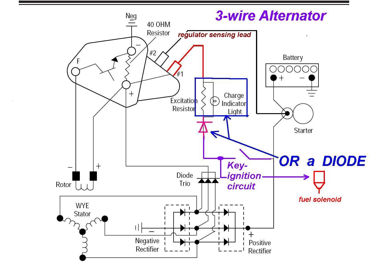
Introduction
The solenoid function in a Cub Cadet mower serves as an electromagnetic remote switch that bridges the high-amperage gap between the battery and the starter motor. Understanding this component matters because failing starter systems often masquerade as dead batteries or ruined starters, leading to unnecessary replacement costs. This electromechanical device is used extensively across small-engine outdoor power equipment to protect delicate ignition switches from heavy electrical loads. Comprehending how this circuit operates improves troubleshooting accuracy, ensures safe handling of 12-volt DC direct current power systems, and streamlines diagnostic workflows on residential and commercial turf equipment.
💡 Technical Key Takeaways:
- Core Focus: Diagnostic schematic and terminal connection layout for Solenoid Function In Cub Cadet Mower.
- Target Scope: Field technicians, automotive DIYers, and residential/commercial electricians.
- Safety Rule: Always disconnect the primary power source/battery terminal and verify zero voltage with a multimeter before touching wires.
Core Concepts and Wiring Fundamentals
Outdoor power equipment relies on a low-current control circuit to manage a high-current load circuit through a specialized relay mechanism. When the operator turns the ignition key to the start position, a low-amperage signal travels from the switch through safety interlock switches—such as the seat, brake, and PTO power take-off switches—before reaching the small activation terminal on the starter solenoid. This low-current flow energizes a fine-wire coil wrapped around an iron core inside the housing.
Energizing the internal coil generates a magnetic field that pulls a movable iron plunger downward against a spring return. Copper contact discs attached to the base of this plunger bridge the two large threaded terminals on the outer housing. One large terminal connects directly via heavy-gauge copper cabling to the positive battery post, while the other runs straight to the starter motor armature. Once these heavy contacts close, a surge of direct current often exceeding one hundred amperes rushes directly to the starter motor, cranking the engine.
The entire system depends on a robust chassis ground to complete the control circuit. On many lawn tractors, the solenoid body bolts directly to the grounded metal frame, though separate ground wires are frequently integrated into the main wiring harness to prevent high-resistance corrosion paths. Fuses, typically rated between 10 and 20 amperes depending on the specific model, protect the low-current ignition feed from short circuits. Technicians studying these layouts often reference Relay and Component Wiring Diagrams to trace how control signals manipulate heavy power loads.
[Finding] — According to data compiled by the Consumer Product Safety Commission (CPSC) and electrical safety organizations, uninsulated high-amperage connections left exposed to lawn debris and moisture are a primary catalyst for equipment electrical fires.
Diagram Explanation and Key Components
Interpreting schematics for the solenoid function in a Cub Cadet mower requires familiarity with standardized automotive and small-engine electrical symbols. The solenoid appears as a rectangular or cylindrical block containing a winding coil symbol connected to two small control terminals, paired with an open switch symbol bridging two heavy-gauge power studs. Standard SAE Society of Automotive Engineers guidelines dictate wire color conventions, though manufacturers frequently deviate based on harness production dates. Typically, heavy unswitched battery feeds appear as solid red wires, while switched ignition control lines utilize yellow wires with black tracers.
Reading these diagrams involves tracing power flow from the battery positive terminal, through the main circuit breaker or fuse, into the ignition switch assembly, and outward through the safety module. The safety module acts as a logical gatekeeper; if the operator is not seated or the parking brake is disengaged, the circuit opens, preventing the control voltage from reaching the solenoid coil. Reviewing Vehicle Wiring Diagrams helps technicians grasp this identical series-parallel logic applied to larger automotive starter systems. Every component symbol on the schematic correlates directly to a physical part on the machine, allowing structured tracing during diagnostics.
Common Problems and Troubleshooting Methods
Typical faults in this circuit include internal contact welding, open-circuit coil windings, corrosion at high-amp terminal studs, and low control voltage caused by failing safety switches. A methodical diagnostic approach prevents misdiagnosis of expensive parts like starter assemblies. First, verify the battery state of charge using a digital multimeter set to measure DC voltage, ensuring a resting reading of approximately 12.6 volts. Next, test for voltage drop across the heavy terminals while an assistant attempts to engage the starter.
When the key is turned to start, a distinct clicking sound indicates that the low-current control circuit and internal coil are functioning properly, but a lack of engine cranking points toward burned internal contact discs or a failing starter motor. If the unit remains completely silent upon turning the key, the technician must check for control voltage at the small exciter terminal using a test light or multimeter. The absence of control voltage shifts the diagnosis backward into the safety interlock switches, the fuse block, or the ignition switch itself. For broader context on isolating continuity breaks, consult resources on Wiring Troubleshooting.
Practical Tips and Safety Considerations
Working on 12-volt direct current circuits demands respect for the immense amperage a lead-acid battery can deliver into a dead short. Technicians and DIY enthusiasts alike must always disconnect the negative battery cable before servicing starter components, replacing harnesses, or tightening terminal nuts. A dropped wrench bridging the unswitched battery stud to the unpainted steel frame can instantly weld tools, melt wire insulation, or cause severe burns. Furthermore, applying a thin coating of dielectric grease to terminal posts after tightening prevents moisture intrusion and retards the formation of high-resistance copper oxide.
When replacing a failed unit, verify that the replacement part matches the exact terminal configuration and internal grounding style of the original equipment. Some aftermarket units feature isolated ground studs requiring an external ground wire, whereas factory units often rely on metal-to-metal contact with the mounting bracket. Ignoring these minute structural differences leads to intermittent cranking issues or blown fuses. Proper torque specifications on terminal nuts prevent stripped threads while maintaining low electrical resistance across the heavy power path.
Conclusion
Mastering the solenoid function in a Cub Cadet mower empowers mechanics and hobbyists to diagnose starting system failures with confidence and precision. By breaking down the system into low-current control paths and high-current power loads, technicians can rapidly isolate whether a fault originates in a safety switch, the control wiring, or the internal contacts of the relay itself. Adhering to safety protocols regarding battery disconnection and terminal insulation ensures safe, efficient repairs. To expand technical knowledge across other electrical systems, review foundational principles found in Wiring Diagram Basics.
Quick Wiring Specifications & Terminal Guide
| Component / Circuit | Standard Wire Gauge | Recommended Protection |
|---|---|---|
| Control & Trigger Signals | 18 – 20 AWG | 5A – 7.5A Inline Fuse |
| Standard Auxiliary Load | 14 – 16 AWG | 15A – 20A Circuit Breaker |
| Main Power Feed / Supply | 10 – 12 AWG | 30A – 40A Heavy-Duty Relay |
Images References