Introduction
Mastering how to wire a 12 volt ford alternator is essential for restoring reliable electrical charging performance to classic vehicles, custom builds, and industrial equipment. This mechanical process involves routing high-current outputs and low-current excitation circuits to convert rotational mechanical energy into regulated direct current (DC) electrical power. Proper installation prevents battery drain, protects against catastrophic harness meltdowns, and ensures the vehicle maintains system voltage above twelve point six volts while running. Technicians working on these vintage or modified charging systems must understand both internal and external voltage regulator configurations to guarantee correct operation. Accurate wiring practices improve diagnostic accuracy, reduce resistance heating in high-amperage pathways, and safeguard sensitive electronic components throughout the chassis. For broader applications involving auxiliary equipment, referencing Vehicle Wiring Diagrams provides additional clarity on integrating charging circuits with main distribution buses.
💡 Technical Key Takeaways:
- Core Focus: Diagnostic schematic and terminal connection layout for How To Wire A 12 Volt Ford Alternator.
- Target Scope: Field technicians, automotive DIYers, and residential/commercial electricians.
- Safety Rule: Always disconnect the primary power source/battery terminal and verify zero voltage with a multimeter before touching wires.
Core Concepts and Wiring Fundamentals
Understanding the basic architecture of vintage Ford charging setups begins with differentiating between external regulator systems, such as the classic Ford 1G layout, and later internal regulator designs like the 3G series. The alternator functions by spinning a rotor inside a stator, creating alternating current that internal diodes rectify into direct current. A battery cable, designated as the main output or BAT terminal, carries this rectified current directly to the starter relay or positive battery terminal. This heavy-gauge conductor must match the maximum amperage output of the unit to prevent dangerous voltage drops and thermal overload under heavy electrical loads. Low-current control circuits, including the field (F) and stator (S) or indicator (I) terminals, manage magnetic field strength inside the rotor to regulate output voltage.
Control circuits rely on switched ignition power and proper grounding to function reliably. Voltage regulation is achieved by modulating the current sent to the field winding, which dictates the strength of the magnetic field and dictates overall output. If the reference voltage drops, the regulator increases field current to boost output. Conversely, fully charged batteries reduce field current to prevent overcharging. Maintaining low resistance across every connection point is critical, as high resistance causes heat generation and erratic voltage regulation. Ground continuity is equally vital; charging units mounted on rubber bushings or painted brackets often require a dedicated ground strap running directly from the alternator housing to the engine block or battery negative terminal.
[Society of Automotive Engineers (SAE) Standard J1128] — Establishes specifications for low-voltage primary electrical cables, detailing insulation thickness, conductor stranding, and temperature ratings required for safe automotive wiring installations.
Diagram Explanation and Key Components
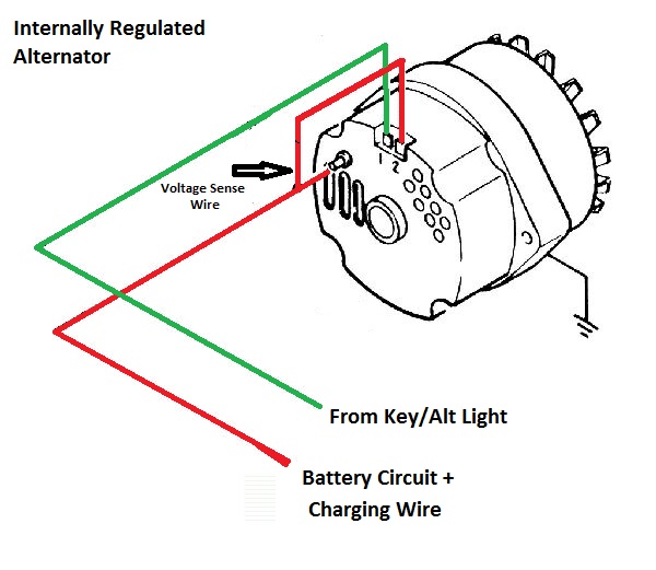
Reading a schematic for how to wire a 12 volt ford alternator requires identifying standardized terminal markings and symbolic representations of diodes, regulators, and fusible links. The output terminal is typically labeled BAT or B+ and connects via a heavy-gauge copper conductor protected by a fusible link or dedicated megafuse. External regulator setups utilize a plug with letters such as A, F, S, and I. The A terminal monitors system voltage, the F terminal connects to the alternator field, the S terminal senses stator output to control the charge indicator lamp or choke relay, and the I terminal energizes the regulator upon ignition activation. Internal regulator versions simplify this by housing the control circuitry inside the alternator housing, reducing external wiring to a primary output stud and a small connector plug.
Color coding on vintage Ford harnesses generally employs yellow with a white stripe for the main voltage sensing wire, orange with a blue stripe for the field circuit, and white with a black stripe for the stator tap, though aftermarket replacement harnesses may vary. Interpreting these lines accurately prevents crossed circuits that can instantly destroy solid-state voltage regulators or diodes. When dealing with relay-assisted or modified setups, reviewing resources like Relay and Component Wiring Diagrams helps clarify how auxiliary warning lights and ignition excitation circuits interact with the primary charging loop. Technicians should always verify terminal designations physically on the hardware rather than relying solely on generic color codes, as previous owners or aftermarket modifications often alter factory wiring colors.
Common Problems and Troubleshooting Methods
Diagnosing charging system failures involves a systematic approach to identifying open circuits, high-resistance connections, faulty diodes, and failing voltage regulators. A common real-world observation involves intermittent no-charge conditions caused by corrosion accumulation inside the multi-pin regulator plug or loose mounting bolts that compromise the chassis ground. When a vehicle exhibits a discharged battery or dim dashboard illumination, initial diagnosis starts with measuring resting battery voltage, followed by testing system voltage while the engine idles. A healthy charging system should register between thirteen point five and fourteen point five volts across the battery terminals with accessories running.
If voltage remains below battery resting levels, technicians perform a voltage drop test across the main output cable and ground paths to isolate excessive resistance. An excessive drop exceeding zero point two volts on the positive charging cable indicates a compromised connection, corroded terminal lug, or undersized conductor. Testing the field circuit with a multimeter helps determine whether the regulator is successfully commanding the rotor to magnetize. If the field circuit lacks power with the ignition switch in the run position, the fault lies within the ignition switch feed, blown fuse, or damaged wiring harness. Complex diagnostic procedures and systematic fault tracing techniques are thoroughly outlined in Wiring Troubleshooting guides, providing structured pathways to isolate root causes without replacing unnecessary parts.
Practical Tips and Safety Considerations
Executing a clean installation demands proper wire sizing, secure mechanical crimps, high-temperature split-loom insulation, and strict adherence to automotive electrical safety protocols. Because a direct short from the alternator output stud to ground can deliver hundreds of amperes instantly—capable of melting copper wire and starting fires—always disconnect the negative battery cable before servicing any charging system components. Utilize marine-grade tinned copper wire and heat-shrink terminals sealed with adhesive lining to prevent moisture ingress and subsequent corrosion in harsh under-hood environments. Secure all wiring away from hot exhaust manifolds, sharp sheet metal edges, and moving pulley assemblies using insulated P-clamps and zip ties.
When upgrading older external regulator setups to high-output internal regulator units, technicians must bypass or disconnect the old mechanical regulator box to prevent conflicting control signals and system instability. Ensure that the chosen wire gauge matches or exceeds the maximum output rating of the alternator; for instance, a one-hundred-ampere unit requires heavy-gauge wiring to prevent dangerous overheating. Always torque mechanical fasteners to manufacturer specifications to guarantee solid electrical contact. Ground continuity must be verified using a low-resistance ohmmeter before applying power. Following established guidelines from organizations like the National Fire Protection Association (NFPA) regarding vehicle electrical safety minimizes risk and ensures long-term operational reliability.
Conclusion
Mastering how to wire a 12 volt ford alternator bridges the gap between mechanical restoration and reliable electrical engineering. Proper component identification, accurate schematic interpretation, and meticulous attention to wire gauge and grounding eliminate chronic charging failures. By systematically diagnosing voltage drops and securing high-current connections against thermal and environmental degradation, technicians ensure safe, efficient power delivery. Adhering to professional installation standards protects sensitive electronics and extends the operational lifespan of the entire charging circuit. Reviewing foundational resources like Wiring Diagram Basics further strengthens diagnostic competency for all subsequent automotive electrical projects.
Quick Wiring Specifications & Terminal Guide
| Component / Circuit | Standard Wire Gauge | Recommended Protection |
|---|---|---|
| Control & Trigger Signals | 18 – 20 AWG | 5A – 7.5A Inline Fuse |
| Standard Auxiliary Load | 14 – 16 AWG | 15A – 20A Circuit Breaker |
| Main Power Feed / Supply | 10 – 12 AWG | 30A – 40A Heavy-Duty Relay |
Images References