Introduction
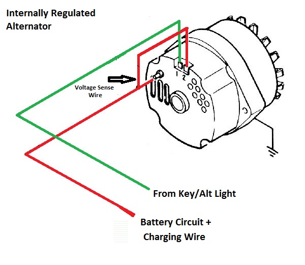
An alternator generator wiring diagram serves as the definitive technical roadmap for understanding, installing, and servicing the vehicle charging system. This schematic maps the electrical pathway between the engine-driven charging unit, the starter battery, and all onboard electrical loads. Mastering this layout ensures proper current flow, prevents catastrophic short circuits, and allows technicians to diagnose charging failures accurately in 12V and 24V automotive or industrial environments. Vehicles operating across the US, UK, Canada, and Australia rely on these visual guides to maintain stable system voltage and protect sensitive electronic control modules from destructive voltage spikes.
💡 Technical Key Takeaways:
- Core Focus: Diagnostic schematic and terminal connection layout for Alternator Generator Wiring Diagram.
- Target Scope: Field technicians, automotive DIYers, and residential/commercial electricians.
- Safety Rule: Always disconnect the primary power source/battery terminal and verify zero voltage with a multimeter before touching wires.
Core Concepts and Wiring Fundamentals
The vehicle charging circuit converts mechanical engine energy into alternating current via electromagnetic induction, rectifies that current into direct current, and regulates output to replenish the battery. Heavy-gauge copper cables handle the high-amperage output from the charging unit directly to the starter motor terminal or positive battery post. Thinner control wires link internal or external voltage regulators to the ignition switch and dashboard warning indicators.
Fuses, fusible links, and dedicated high-current relays protect these circuits from thermal overload. A secure chassis ground completes the electrical circuit, allowing return current to flow safely back to the negative battery terminal. High-resistance connections at the alternator housing or engine block remain a frequent source of voltage drop, starving the battery of proper charging current despite a functional generator.
[Charging System Failures] — Society of Automotive Engineers (SAE) technical data indicates that a significant percentage of premature alternator replacements stem from corroded external cable connections and poor chassis grounds rather than internal component failure.
Diagram Explanation and Key Components
Reading an alternator generator wiring diagram requires familiarity with standardized automotive symbols representing windings, diodes, brushes, and solid-state regulator chips. The primary output terminal is typically labeled B+ (Battery Positive), while the field terminal is marked F, and the stator or auxiliary terminal carries the STA or D+ designation. Indicator lamp circuits often complete a ground path through the regulator until the unit begins producing voltage, at which point the light extinguishes.
Wire color codes vary significantly between North America, the UK, and Australia, requiring careful cross-reference with manufacturer service literature. For example, heavy battery feeds are universally red or uninsulated copper braid, but ignition-switched excitation wires and sensor leads differ across Ford, General Motors, European, and Asian platforms. Reference documentation such as Vehicle Wiring Diagrams provides further insight into navigating these manufacturer-specific schematics.
Common Problems and Troubleshooting Methods
Systematic fault-finding on a charging circuit involves isolating voltage output issues from battery degradation and wiring faults using a Digital Multimeter. A methodical diagnostic process starts by verifying battery state of charge with the engine off, followed by measuring charging voltage across the battery terminals with the engine running under electrical load. Readings outside standard manufacturer thresholds point toward failed internal diodes, a worn voltage regulator, or excessive resistance in the main output cable.
Open circuits in the field excitation wire prevent the alternator from turning on, while high resistance in the ground circuit causes undercharging symptoms. Technicians should utilize voltage drop testing across the positive feed and negative ground paths to pinpoint hidden corrosion before condemning expensive hardware. Comprehensive guides on Wiring Troubleshooting offer additional methodologies for isolating intermittent electrical faults.
Practical Tips and Safety Considerations
Automotive electrical work demands strict adherence to safety protocols due to the presence of unswitched battery power capable of delivering hundreds of amperes of fault current. Always disconnect the negative battery cable before servicing alternator connections to prevent accidental arcing against the chassis or engine block. Ensure replacement cables match the original cross-sectional area and ampacity rating specified by the manufacturer to prevent dangerous thermal buildup and insulation melting.
Regional standards, such as ABYC guidelines for marine applications or local automotive repair regulations, dictate proper terminal crimping techniques and marine-grade tinned copper utilization in harsh environments. Never disconnect a battery while the engine runs to test a charging system, as modern semiconductor components can be destroyed by resulting inductive voltage transients. For related auxiliary power setups, consult resources covering Relay and Component Wiring Diagrams.
Conclusion
Interpreting an alternator generator wiring diagram bridges the gap between guesswork and precise electrical diagnosis in modern transport and industrial equipment. Respecting high-amperage pathways, verifying ground integrity, and following systematic testing procedures protect both the technician and the vehicle infrastructure. Careful study of these schematics ensures reliable charging performance and extends the operational lifespan of the entire electrical grid.
Quick Wiring Specifications & Terminal Guide
| Component / Circuit | Standard Wire Gauge | Recommended Protection |
|---|---|---|
| Control & Trigger Signals | 18 – 20 AWG | 5A – 7.5A Inline Fuse |
| Standard Auxiliary Load | 14 – 16 AWG | 15A – 20A Circuit Breaker |
| Main Power Feed / Supply | 10 – 12 AWG | 30A – 40A Heavy-Duty Relay |
Images References