Introduction
The 4 pin relay diagram working principle governs how an electromechanical switch uses a low-current circuit to control a high-current load safely and efficiently. Understanding this component is essential for preventing voltage drop, protecting delicate dashboard switches in modern vehicles, and managing heavy electrical loads in industrial equipment. Relays act as the bridge between two entirely separate electrical circuits. Mastering their configuration ensures reliable installations across automotive, marine, and industrial environments. Whether modifying a custom harness or diagnosing an intermittent power failure, knowledge of these electromechanical control devices prevents costly wiring damage and electrical fires.
💡 Technical Key Takeaways:
- Core Focus: Diagnostic schematic and terminal connection layout for 4 Pin Relay Diagram Working Principle.
- Target Scope: Field technicians, automotive DIYers, and residential/commercial electricians.
- Safety Rule: Always disconnect the primary power source/battery terminal and verify zero voltage with a multimeter before touching wires.
Core Concepts and Wiring Fundamentals
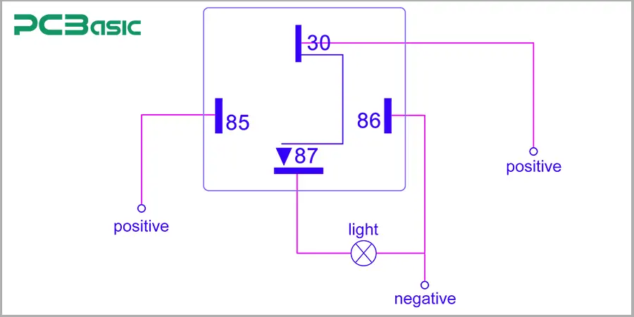
A standard 4-pin automotive or industrial relay splits an electrical system into two distinct loops: a low-power control circuit and a high-power load circuit. The control circuit utilizes thin-gauge wire connected to a switch or electronic control module, while the load circuit uses thick-gauge cable capable of handling substantial amperage without overheating. Power feeds from a battery through a fuse to the heavy-duty contacts, while the control side energizes a microscopic copper coil. When current flows through this coil, it generates a localized electromagnetic field.
This magnetic flux pulls a spring-loaded iron armature downward, forcing physical internal contacts to close and complete the heavy-duty circuit. Once the control switch opens, the magnetic field collapses instantly, and a tension spring returns the armature to its resting position. Standardizing this layout requires adherence to automotive and industrial standards, such as those published by the Society of Automotive Engineers (SAE) for terminal identification. Proper integration depends heavily on matching wire gauge to expected ampacity, ensuring secure terminal crimps, and utilizing robust chassis grounds to maintain circuit integrity.
Relay failure analysis frequently indicates that excessive coil voltage spikes or moisture intrusion into unsealed terminal blocks account for a significant percentage of premature component replacements in mobile electrical architectures. — Society of Automotive Engineers (SAE)
Diagram Explanation and Key Components
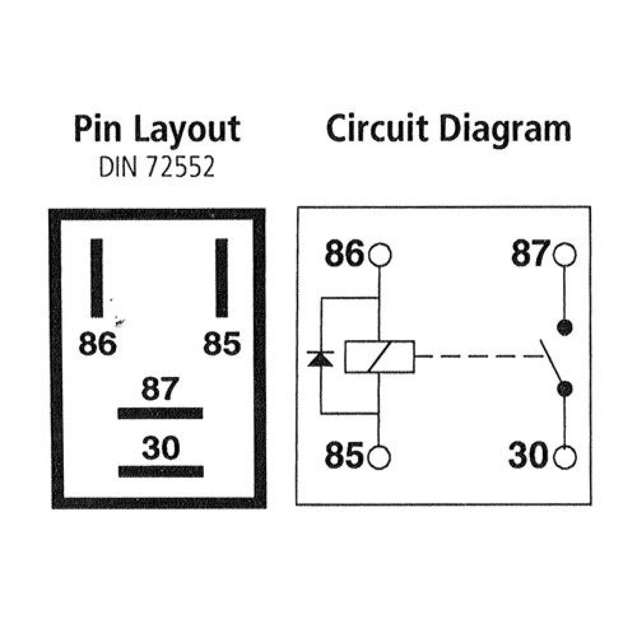
Standardized terminal numbering simplifies reading a 4 pin relay diagram working principle across various manufacturers and global markets. Pin 85 serves as the ground or negative trigger for the internal electromagnetic coil, whereas Pin 86 acts as the positive feed originating from the dashboard toggle switch or relay driver. On the high-current side, Pin 30 receives constant or switched battery power directly from a fused power distribution center. Pin 87 represents the normally open output terminal that routes power directly to the target accessory, such as auxiliary driving lights, electric cooling fans, or fuel pumps.
Schematics illustrate these components using standardized symbols, displaying the coil as a coiled line or box and the switch contacts as a movable blade. Technicians evaluating Relay and Component Wiring Diagrams must verify whether a specific part includes an internal suppression diode or resistor across pins 85 and 86. This built-in protection device safely absorbs transient voltage spikes generated when the coil de-energizes, protecting sensitive semiconductor controllers from electrical feedback. Regional variations in wiring documentation may alter line weights or symbol orientations, but the underlying terminal numbering convention remains universally consistent for standard single-pole single-throw electromechanical relays.
Common Problems and Troubleshooting Methods
Systematic diagnostic procedures for relay circuits require a digital multimeter configured to measure DC voltage and circuit continuity. A common failure mode involves a blown inline fuse protecting the main power feed to Pin 30, which cuts off power to the load entirely without damaging the relay itself. Another frequent issue is a corroded terminal connection on Pin 85 or Pin 86, resulting in a weak magnetic field that fails to pull the internal contacts closed, often heard as a rapid clicking sound.
A structured testing workflow begins by confirming battery voltage present at Pin 30 relative to a solid chassis ground. Next, activate the control switch and verify that system voltage reaches Pin 86 while a stable ground is verified at Pin 85. If control voltage and ground are present but Pin 87 shows no output when the relay clicks, the internal contacts have likely pitted or welded together due to an overcurrent condition. Technicians exploring Wiring Troubleshooting techniques should always perform voltage drop tests across the relay contacts under a real load rather than relying solely on simple continuity checks with the power disconnected.
Practical Tips and Safety Considerations
High-current automotive and industrial wiring demands strict adherence to safety protocols to prevent severe burns, component destruction, and electrical fires. Before servicing any relay center, disconnect the primary battery negative terminal or pull the main system fuse to de-energize the harness completely. Always verify circuit de-energization using a calibrated digital multimeter or test light. When selecting replacement relays, match the amperage rating stamped on the housing to the maximum load draw of the connected device, never substituting a lower-rated component.
Install relays in upright or inverted positions with the wire entry points facing downward when exposed to the elements, preventing moisture and road salt from pooling inside the connector cavity. Use weather-pack or sealed relay sockets in damp locations, and apply dielectric grease sparingly to terminal pins to inhibit oxidation. Ensure that control wiring remains separated from high-tension ignition leads or noisy alternator lines to prevent electromagnetic induction from triggering unintended switching. For complex setups, consulting Vehicle Wiring Diagrams ensures proper integration with factory multiplexed computer networks.
Conclusion
Grasping the mechanics of control and load separation empowers technicians and DIY builders to design bulletproof electrical systems. Correctly interpreting terminal numbers, sizing wires appropriately, and utilizing structured diagnostic steps eliminate guesswork during maintenance. Prioritizing safety and proper component selection guarantees long-term reliability in demanding environments. Reviewing Wiring Diagram Basics further strengthens foundational skills needed for successful electrical installations.
Quick Wiring Specifications & Terminal Guide
| Component / Circuit | Standard Wire Gauge | Recommended Protection |
|---|---|---|
| Control & Trigger Signals | 18 – 20 AWG | 5A – 7.5A Inline Fuse |
| Standard Auxiliary Load | 14 – 16 AWG | 15A – 20A Circuit Breaker |
| Main Power Feed / Supply | 10 – 12 AWG | 30A – 40A Heavy-Duty Relay |
Images References