Introduction
An ezgo key switch breakdown describes the mechanical or electrical failure of the ignition switch assembly utilized in EZ-GO golf carts and utility vehicles. These low-voltage DC direct current electrical systems rely on the key switch to route control voltage from the battery pack or accessory circuit to the solenoid or controller, initiating vehicle movement. Understanding how this component fails and how to test it improves diagnostic accuracy, prevents unnecessary part replacements, and ensures safe operation across diverse utility and recreational applications in North America, the UK, and Australasia.
💡 Technical Key Takeaways:
- Core Focus: Diagnostic schematic and terminal connection layout for Ezgo Key Switch Breakdown.
- Target Scope: Field technicians, automotive DIYers, and residential/commercial electricians.
- Safety Rule: Always disconnect the primary power source/battery terminal and verify zero voltage with a multimeter before touching wires.
Core Concepts and Wiring Fundamentals
Golf cart electrical systems operate primarily on low-voltage DC power, typically ranging from 36 volts to 48 volts in electric models, or 12 volts in gas-powered variants. The key switch functions as a master control point, interrupting the low-current control circuit rather than carrying the heavy motor load directly. When the key turns to the “ON” position, internal contacts close, permitting current to flow through specific wire harnesses to energize the main solenoid or engine ignition circuit.
Wire color codes and terminal designations vary depending on the specific model year and drive type, whether series, solid-state speed controller, or AC drive. Technicians must consult the appropriate Vehicle Wiring Diagrams to verify correct circuit paths. Because these vehicles operate outdoors, terminals frequently experience oxidation, moisture ingress, and vibration-induced fatigue at the crimp connectors.
[Vehicle electrical system failures, particularly involving low-voltage DC control circuits and switches, are frequently traceable to high resistance caused by environmental corrosion and loose mechanical connections] — [Society of Automotive Engineers (SAE) Technical Guidelines]
Diagram Explanation and Key Components
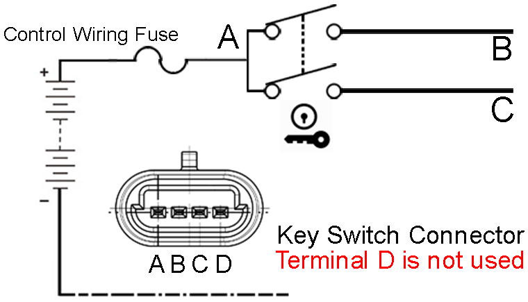
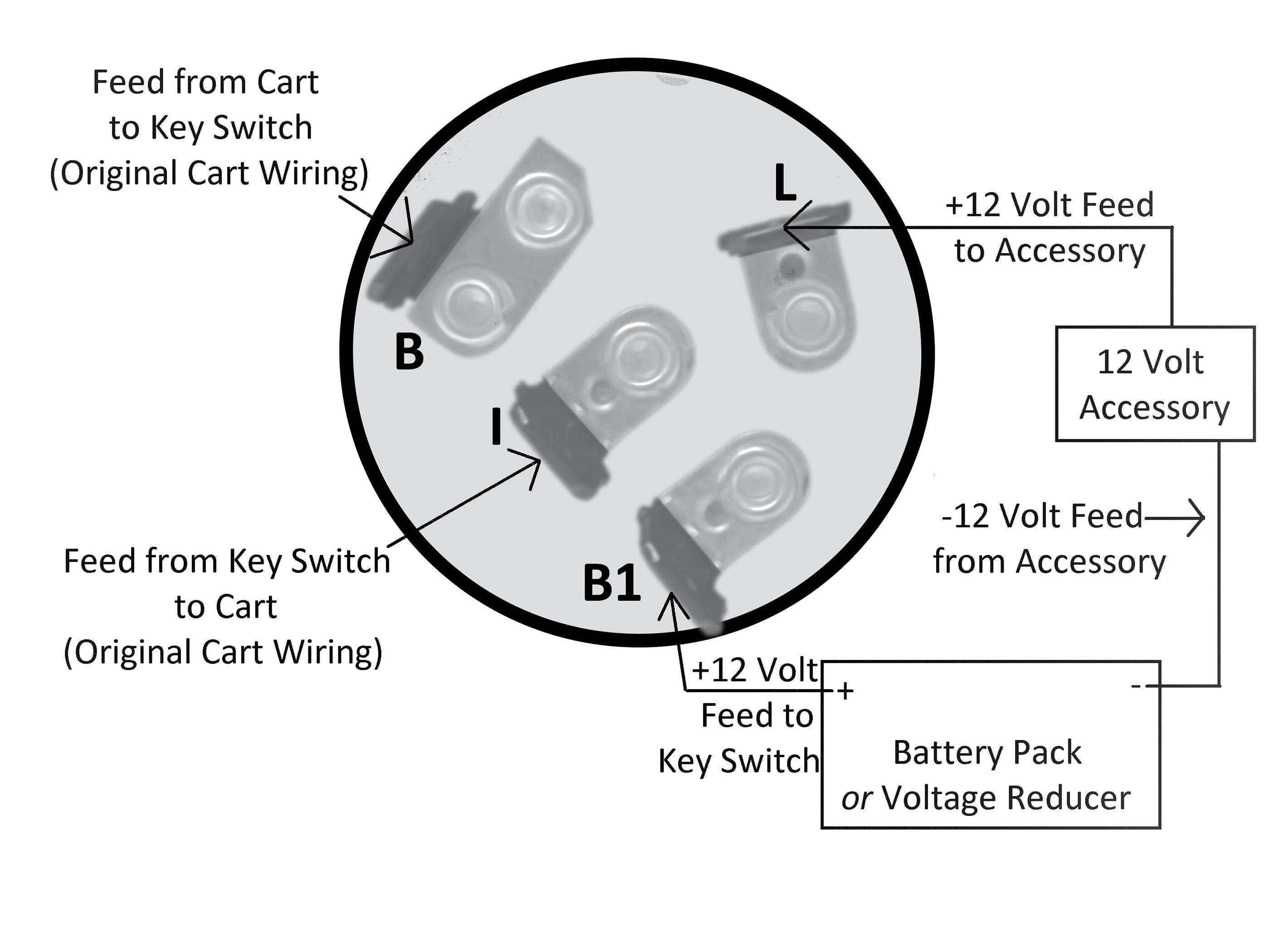
Reading a schematic for an ezgo key switch breakdown involves identifying standardized symbols for rotary switches, normally open contacts, and multi-pin terminal blocks. A standard EZ-GO key switch typically features two or three distinct terminals, commonly labeled Battery (B), Ignition (I), and Accessories (A), or designated by numerical markings such as Terminal 1, 2, and 3. The schematic lines represent physical copper conductors, while intersecting dots denote spliced junctions.
To interpret these drawings correctly, technicians rely on foundational principles found within Wiring Diagram Basics to trace power flow from the source through the switch contacts to downstream components. The diagram illustrates continuity states for every key position—OFF, ON, and sometimes START. Grasping these state changes allows a technician to predict voltage readings at each terminal during active testing.
Common Problems and Troubleshooting Methods
Systematic fault-finding for an ezgo key switch breakdown requires a structured diagnostic approach using a digital multimeter set to measure DC voltage and continuity (ohms). The primary failure modes include internal contact pitting, thermal melting from excessive current draw, spring fatigue, and corroded spade terminals. Technicians must never guess at a diagnosis; instead, they should verify power entering the switch input terminal before checking for voltage output at the switched terminal.
When the vehicle exhibits a complete loss of power, the diagnostic process begins at the battery source and moves methodically through the primary fuse, the key switch, and onward to the Relay and Component Wiring Diagrams governing the main contactor. If voltage is present at the input terminal of the key switch but absent at the output terminal with the key turned to the ON position, internal contact failure is confirmed, necessitating switch replacement.
Practical Tips and Safety Considerations
Automotive and utility vehicle electrical work demands strict adherence to safety protocols, particularly regarding high-capacity DC battery banks which can deliver severe arc flashes if short-circuited. Before servicing any switch or wire harness, technicians must tow/run switch to the “Tow/Maintenance” position on electric models, or disconnect the negative battery terminal on gas models, to de-energize the system completely. Always verify zero voltage with a calibrated meter before touching bare conductors or terminals.
When replacing a failed switch, mechanics should inspect the mating wire terminals for heat damage or greenish copper oxidation. Corroded spade connectors must be cut off and replaced with new, weather-sealed crimp terminals of the correct gauge to prevent high-resistance hotspots. Proper strain relief on the wire harness prevents vibration from fatiguing the newly installed connections.
Conclusion
Mastering the diagnostic procedures for an ezgo key switch breakdown ensures rapid identification of electrical faults and minimizes unnecessary downtime for utility and recreational vehicles. By combining methodical multimeter testing with accurate schematic interpretation, technicians maintain high standards of reliability and safety. For further guidance on diagnosing complex electrical faults across various applications, review the resources available at Wiring Troubleshooting.
Quick Wiring Specifications & Terminal Guide
| Component / Circuit | Standard Wire Gauge | Recommended Protection |
|---|---|---|
| Control & Trigger Signals | 18 – 20 AWG | 5A – 7.5A Inline Fuse |
| Standard Auxiliary Load | 14 – 16 AWG | 15A – 20A Circuit Breaker |
| Main Power Feed / Supply | 10 – 12 AWG | 30A – 40A Heavy-Duty Relay |
Images References