Security cameras are essential for protecting homes and businesses. Zosi cameras are a popular choice, known for their reliability and ease of use. A crucial aspect of setting up a Zosi camera system is understanding the zosi camera wiring diagram. This article breaks down the importance of wiring diagrams, explains how to read them, and provides helpful tips for a successful installation.
Why a Wiring Diagram Matters
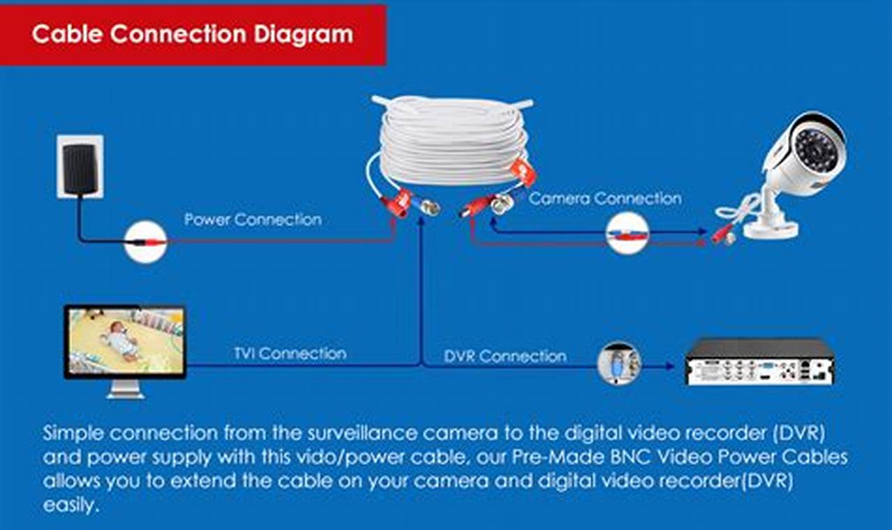
The wiring diagram is the roadmap for connecting your Zosi camera system. It clearly illustrates how each component the camera, DVR (Digital Video Recorder), power supply, and any other accessories should be connected. Correct wiring ensures that the cameras function properly, delivering clear video footage and reliable performance. Without a wiring diagram, you risk incorrect connections, which could lead to camera malfunction, system instability, or even damage to your equipment. A solid understanding of the diagram can also simplify troubleshooting if any issues arise after installation.
Key Benefits of Using a Zosi Camera Wiring Diagram
Using a zosi camera wiring diagram offers several significant benefits. First, it minimizes the risk of errors during installation. By following the diagram step-by-step, you can ensure that each connection is made correctly, avoiding potential problems. Second, it saves time and effort. Instead of guessing or experimenting with different wiring configurations, the diagram provides a clear and concise guide, streamlining the installation process. Third, it enables you to diagnose and resolve issues more efficiently. If a camera stops working, the wiring diagram can help you quickly identify potential points of failure and trace the connections to find the root cause.
Understanding the Structure of a Wiring Diagram
A typical zosi camera wiring diagram is a visual representation of the connections between various components. It typically includes symbols representing the camera, DVR, power supply, and cables. Each connection is clearly indicated by lines, with labels specifying the type of cable (e.g., coaxial cable, Ethernet cable, power cable) and the corresponding connectors. The diagram will also show the polarity of power connections, which is crucial for preventing damage to the equipment. Some diagrams may also include information about grounding and shielding to minimize interference and ensure optimal video quality. Different Zosi camera models might have slightly different wiring requirements, so always refer to the diagram specific to your model.
How to Read a Zosi Camera Wiring Diagram
Reading a zosi camera wiring diagram involves carefully examining the symbols and labels. Start by identifying the key components, such as the camera, DVR, and power supply. Then, trace the lines connecting these components, paying attention to the cable types and connector types. Ensure that you understand the polarity of the power connections (positive and negative). If the diagram includes grounding instructions, follow them carefully. If you’re unsure about any part of the diagram, consult the Zosi camera documentation or seek assistance from a qualified technician. Take it one step at a time, focusing on one connection at a time, and double-check your work as you go.
Tips for Successful Wiring
To ensure a successful Zosi camera wiring experience, consider these additional tips: Always disconnect the power supply before making any connections to avoid electrical shock or damage to the equipment. Use high-quality cables and connectors to ensure reliable signal transmission. Label each cable as you connect it to make it easier to troubleshoot issues later. Protect the cables from damage by routing them carefully and securing them with cable ties. Test the camera system after completing the wiring to ensure that everything is working correctly. Finally, keep a copy of the zosi camera wiring diagram for future reference, especially if you plan to make any changes to the system later on.
