A wiring schematic diagram serves as a vital roadmap for electrical systems, providing a visual representation of connections within a circuit. Understanding this particular diagram type is paramount for ensuring safety, efficiency, and the proper execution of electrical installations and repairs. A misinterpreted or ignored wiring schematic can lead to hazardous conditions, equipment damage, and costly rework. Correctly interpreting a wiring schematic diagram ensures that electrical work adheres to prescribed standards and regulations, avoiding potential risks and liabilities.
Mastering the interpretation of a wiring schematic diagram offers several key benefits. Primarily, it prevents costly errors during installation and troubleshooting. By clearly outlining circuit pathways and component placement, the wiring schematic diagram minimizes the risk of incorrect wiring, which can lead to short circuits, component failure, or even electrical fires. Adherence to electrical codes is also greatly facilitated, as the wiring schematic diagram provides a reference for ensuring compliance with relevant standards. Furthermore, the ability to read and understand a wiring schematic diagram significantly enhances diagnostic skills, enabling technicians to quickly identify and resolve electrical faults, thus reducing downtime and maintenance costs.
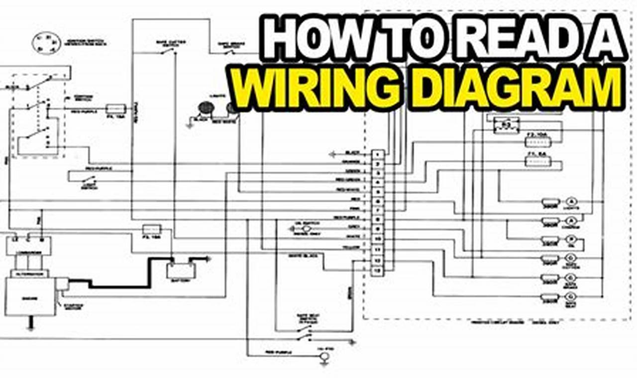
A wiring schematic diagram typically presents a simplified representation of an electrical circuit. This representation makes extensive use of standardized symbols to depict various components such as resistors, capacitors, diodes, transistors, and integrated circuits. Wires are shown as lines connecting these symbols, with the direction of current flow often indicated by arrows. Wire color codes are frequently included to facilitate identification during physical wiring. Connection points, such as terminal blocks and connectors, are clearly marked. Important features, such as relays, fuses, circuit breakers, and grounding symbols, are also prominently displayed to illustrate protective measures and system grounding arrangements. Understanding these symbolic representations is crucial for accurate interpretation.
To effectively interpret and use a wiring schematic diagram, a systematic approach is recommended. Begin by identifying the power source and tracing the circuit pathways logically from the source to the load. Pay close attention to component symbols and their corresponding functions within the circuit. Double-check the voltage and current ratings of components to ensure compatibility with the circuit’s operating parameters. Use a multimeter to verify voltage levels and continuity at various points in the circuit. When troubleshooting, start by isolating the affected section of the circuit and systematically testing components to identify the source of the fault. Always disconnect power before making any physical changes to the wiring.
For enhanced understanding and accuracy, consult complementary resources such as component datasheets, technical manuals, and online forums. Datasheets provide detailed specifications and operating characteristics of individual components. Technical manuals offer comprehensive information about specific electrical systems and equipment. Tools such as multimeters, circuit testers, and wire strippers are essential for practical application of the information contained within a wiring schematic diagram. Consider exploring various types of electrical diagrams, such as ladder diagrams or block diagrams, to broaden your understanding of electrical systems representation. The IEEE provides valuable resources for standard symbols and practices.
In conclusion, mastering the interpretation of wiring schematic diagrams is invaluable for anyone involved in electrical work. The ability to accurately read and apply these diagrams ensures safety, improves efficiency, and reduces the risk of costly errors. Readers are encouraged to explore additional wiring schematic diagrams and resources to further enhance their electrical knowledge and troubleshooting confidence. Continuous learning and practical experience will solidify these skills, empowering individuals to effectively manage and maintain electrical systems with greater precision and expertise.
