Introduction
Wiring race car ignition switch panel 12v battery configurations involves routing high-current direct current power from a vehicle’s energy storage cell through centralized control switches to vital racing engine systems. This specialized setup replaces standard factory key cylinders with heavy-duty toggle switches, push-button starters, and emergency battery disconnects. Such panels matter because they ensure rapid electrical shutdown during a crash, simplify cockpit operation under extreme driving conditions, and prevent power loss from vibration. This practice finds widespread use in grassroots circuit racing, drag racing, and off-road rallying. Understanding how to properly configure these circuits improves electrical safety, reduces voltage drop, and increases overall race weekend reliability.
💡 Technical Key Takeaways:
- Core Focus: Diagnostic schematic and terminal connection layout for Wiring Race Car Ignition Switch Panel 12V Battery.
- Target Scope: Field technicians, automotive DIYers, and residential/commercial electricians.
- Safety Rule: Always disconnect the primary power source/battery terminal and verify zero voltage with a multimeter before touching wires.
Core Concepts and Wiring Fundamentals
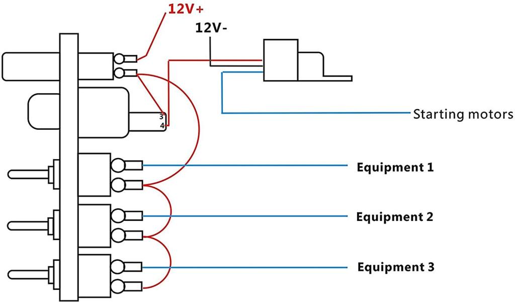
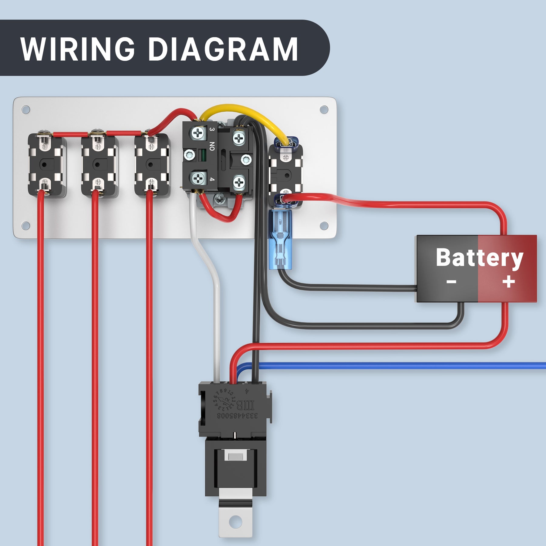
Direct current 12-volt automotive electrical systems rely on a complete circuit loop from the battery positive terminal through protective devices and switches to the electrical load, returning via a dedicated chassis ground. Race car panels typically feature a main battery master disconnect switch, an ignition toggle switch, and a momentary starter push button. Power flows from the battery positive terminal through a heavy gauge primary cable to the master switch, feeding the panel’s main bus bar. Fuses or circuit breakers protect each individual branch circuit downstream from the panel, safeguarding sensitive electronics against accidental overloads and short circuits.
Controlling high-amperage components like electric fuel pumps, ignition boxes, and starter solenoids requires the integration of electromechanical switching devices. Running full operating current directly through a dashboard toggle switch creates excessive resistance and heat. Automotive relays solve this challenge by utilizing low-amperage switch panel circuits to trigger high-current electromagnetic coils, safely switching heavy loads through short, direct power paths. Proper wire gauge selection, determined by total circuit amperage draw and wire length, remains critical to maintaining optimal system voltage and preventing thermal degradation.
Vibration-induced fatigue and terminal corrosion are leading causes of intermittent electrical failure in motorsport wiring harnesses — Vehicle Wiring Diagrams
Diagram Explanation and Key Components
Reading electrical schematics for racing switch panels requires familiarity with standardized symbols representing switches, relays, fuses, and inductive loads. The wiring diagram typically displays a central battery power source feeding a main fused link, followed by parallel branches for ignition, fuel injection, and starter circuits. Standard automotive schematics use specific line weights to differentiate between heavy-gauge power feeds, such as 8 AWG or 4 AWG cables, and thin-gauge control wires, such as 18 AWG or 16 AWG signal leads.
Color coding practices vary globally and by manufacturer, requiring careful verification during any installation. In North America following SAE guidelines, red traditionally denotes battery-positive feeds, while black or bare copper serves as the primary chassis ground. In contrast, European or motorsport-specific harnesses often utilize multicolored striped wires to designate specific subsystem feeds, such as purple for starter solenoid triggers and pink for ignition coil power. Reviewing detailed schematic symbols helps technicians trace continuity accurately before supplying power to newly fabricated harnesses, a process further detailed in Wiring Diagram Basics.
Common Problems and Troubleshooting Methods
Systematic fault-finding in motorsport electrical setups begins with visual inspections followed by voltage drop and continuity testing using a digital multimeter. Typical electrical faults include high-resistance grounds caused by unpainted chassis mounting points, melted insulation from proximity to exhaust headers, and intermittent open circuits resulting from improperly crimped ring terminals. When an engine fails to crank or spark upon flipping the panel switches, the technician must isolate the failure point by checking battery voltage at the main input stud, verifying relay activation, and testing switch continuity.
Diagnostic procedures should follow a logical, step-by-step path starting at the power source and working toward the affected load. First, measure battery voltage at rest and under load to confirm the power supply is viable. Next, verify that control voltage reaches the relay coil when the dashboard toggle switch is activated. If the relay clicks but power fails to reach the component, inspect the output fuse and terminal connections. Technicians seeking advanced diagnostic frameworks often consult professional resources on Wiring Troubleshooting to resolve complex intermittent faults efficiently.
Practical Tips and Safety Considerations
Motorsport electrical installations demand rigorous adherence to professional assembly standards to withstand severe mechanical shock, thermal cycling, and fluid exposure. Mechanics should always disconnect the negative battery terminal before modifying or servicing any part of the vehicle’s electrical infrastructure to prevent accidental arcing or component damage. Utilizing heat-shrink tubing with adhesive lining over all crimped and soldered connections prevents moisture ingress and subsequent copper corrosion. Secure every wire harness using rubber-lined cushioned clamps to prevent chafing against sharp roll cage tubing or aluminum interior panels.
Selecting appropriate wire types is another critical consideration for race applications. Standard household electrical wire is completely unsuited for vehicles due to its rigidity and inability to withstand petroleum-based fluids; technicians must use cross-linked polyethylene insulated wire designed for automotive environments. Furthermore, circuit protection devices such as manual-reset circuit breakers or high-grade fuses must be rated strictly according to the maximum continuous draw of the connected load. Ignoring these sizing rules creates severe fire hazards during a short circuit condition.
Conclusion
Configuring and installing a competition-grade electrical control center requires meticulous planning, correct component selection, and strict adherence to safety protocols. Master control panels enhance driver safety by providing instant power isolation during emergencies while simultaneously streamlining cockpit operations. By understanding fundamental DC circuit principles, utilizing relays for high-amperage loads, and employing systematic diagnostic methods, builders can achieve maximum reliability under punishing track conditions. Proper maintenance of these systems ensures that the vehicle remains competitive and electrically sound throughout the racing season. Explore additional resources on Relay and Component Wiring Diagrams to further expand your knowledge of custom automotive circuits.
Quick Wiring Specifications & Terminal Guide
| Component / Circuit | Standard Wire Gauge | Recommended Protection |
|---|---|---|
| Control & Trigger Signals | 18 – 20 AWG | 5A – 7.5A Inline Fuse |
| Standard Auxiliary Load | 14 – 16 AWG | 15A – 20A Circuit Breaker |
| Main Power Feed / Supply | 10 – 12 AWG | 30A – 40A Heavy-Duty Relay |
Images References