Proper network cabling is the backbone of any reliable data communication system. Understanding the schematic representation that dictates cable termination is essential for anyone involved in network infrastructure, from professional installers to dedicated hobbyists. Mastering these visual guides improves practical cabling skills and enhances overall network performance and stability.
By understanding the principles behind how cables are terminated, individuals gain the ability to effectively troubleshoot network connectivity issues. This deeper comprehension facilitates safer installations, preventing common errors that could lead to data loss or hardware damage. Confident planning of network infrastructure projects becomes readily achievable with a solid grasp of these fundamental visual aids.
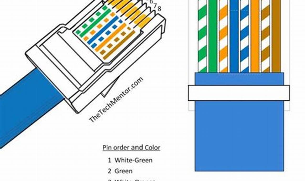
These diagrams typically consist of a visual representation of an eight-position, eight-contact (8P8C) connector, commonly misidentified as a generic “RJ45.” The diagram clearly shows the sequence of colored wires within the cable core. Wires are arranged in a specific order, adhering to either the T568A or T568B standard. These standards dictate which color wire occupies each pin position within the connector. The diagram illustrates the proper insertion of each wire into its corresponding slot, ensuring correct electrical contact. Symbols are straightforward, typically employing color-coded lines to represent each individual wire and a numbered representation for each pin.
To interpret and apply these schematics effectively, begin by identifying whether the diagram adheres to the T568A or T568B standard. Note the color sequence presented and carefully match the corresponding wire to the correct pin. When terminating a cable, ensure that the wires are stripped back to the appropriate length and inserted fully into the connector. Use a crimping tool to securely fasten the connector to the cable, ensuring each pin makes a solid electrical connection. Test the completed cable with a cable tester to verify continuity and correct wiring. For troubleshooting, use the diagram to verify that each wire is in the correct position, correcting any miswirings that are discovered.
When working with network cables, always use high-quality connectors and tools to ensure reliable connections. Practice terminating cables on scrap pieces to hone your skills before working on important projects. Consult online forums or cabling guides for specific advice on advanced techniques such as cable shielding or grounding. Consider exploring other types of cabling schematics, such as those for fiber optic cables or other network topologies, to broaden your understanding. Free online cable testing tools can be useful for initial verification, but professional cable testing equipment often provides more detailed results and diagnostics.
Mastery of these schematic representations is vital for building and maintaining reliable network infrastructures. Continued exploration of related cabling schematics and resources will further enhance expertise and ensure successful implementation of network projects. Readers are encouraged to explore additional network cabling resources for more in-depth knowledge.
