Understanding the electrical blueprint for a compressor unit is a fundamental skill for anyone working with mechanical and electrical systems. Mastering these detailed graphical representations significantly enhances practical electrical knowledge and elevates overall safety standards. These schematics serve as the critical roadmap for connecting and troubleshooting the complex electrical components that power air compression machinery, ensuring reliable operation and preventing costly errors. Acquiring proficiency in interpreting these plans is an essential step towards becoming a more capable and confident professional in the field.
By effectively comprehending the electrical layout of such equipment, numerous benefits can be realized. It enables more efficient and accurate troubleshooting, allowing for rapid diagnosis and resolution of operational issues, thereby minimizing downtime. Furthermore, it ensures safer installations by providing precise instructions for proper component placement and connection, drastically reducing the risk of electrical hazards. This knowledge also empowers individuals to plan electrical projects with greater confidence and precision, whether for new installations, upgrades, or routine maintenance, leading to more robust and dependable systems.
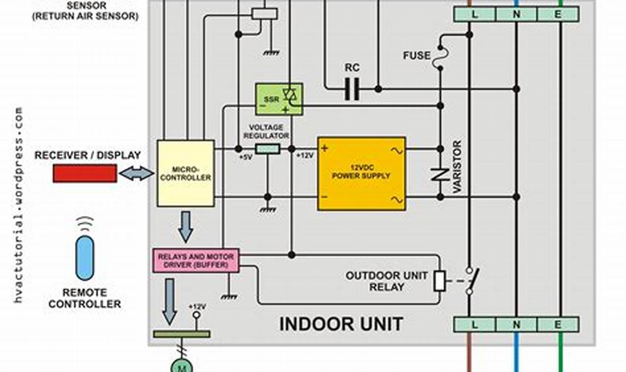
The basic structure of electrical schematics for these systems typically includes a power supply section, control circuitry, and motor protection elements. Common symbols represent components such as electric motors, contactors, thermal overload relays, pressure switches, safety devices, and various types of sensors and indicators. Lines depict electrical pathways, with specific notations indicating wire numbers, terminal points, and voltage levels. Understanding these standardized symbols and their arrangement within the diagram is paramount to deciphering the functional logic of the equipment’s electrical operations.
To effectively read and apply these detailed circuit plans in real-world situations, a systematic approach is recommended. Begin by identifying the main power input and tracing the power distribution throughout the system. Next, focus on the control circuit, understanding how various switches and sensors activate and deactivate components like the motor. Pay close attention to safety interlocks and protective devices, recognizing their role in preventing damage and ensuring user safety. Practical tips include following the flow from left to right and top to bottom, using color-coding where applicable, and verifying connections against the physical installation to ensure accuracy and compliance with safety standards.
Further enhancing one’s understanding of these electrical configurations involves exploring complementary resources. Always ensure power is disconnected before working on any electrical system, and verify with a multimeter. Reviewing similar electrical schematics for different types of motor control circuits, such as those for HVAC systems or industrial pumps, can broaden one’s comprehension of control logic. Consulting industry-specific manuals and textbooks on industrial electricity or motor control offers deeper theoretical insight. Online platforms and simulation software can also provide valuable opportunities for practice and visualization, solidifying the learning process.
Mastering the intricacies of electrical schematics for compressor units is undeniably a cornerstone skill for anyone involved in their maintenance or installation. This proficiency not only ensures the safe and efficient operation of vital equipment but also significantly expands one’s overall electrical expertise. Continued exploration of various electrical resources and diagrams is highly encouraged to further develop these critical abilities. Many more wiring resources and diagrams can be found and explored on readwires.com.
