Introduction
Wire harness drawing symbols serve as the universal vocabulary for reading, interpreting, and troubleshooting complex electrical installations across automotive, residential, and industrial environments. Mastery of these schematic markers enables technicians to trace circuits efficiently, prevent dangerous wiring mistakes, and decode manufacturer documentation without guesswork. Whether planning a custom automotive restoration or examining Vehicle Wiring Diagrams, understanding how graphic representations translate into physical copper paths remains a fundamental skill for safe and accurate electrical work.
💡 Technical Key Takeaways:
- Core Focus: Diagnostic schematic and terminal connection layout for Wire Harness Drawing Symbols.
- Target Scope: Field technicians, automotive DIYers, and residential/commercial electricians.
- Safety Rule: Always disconnect the primary power source/battery terminal and verify zero voltage with a multimeter before touching wires.
Core Concepts and Wiring Fundamentals
An electrical schematic acts as a roadmap, transforming physical hardware into standardized glyphs that represent voltage sources, current paths, protective devices, and loads. In low-voltage direct current systems found in vehicles, power travels from a battery or alternator through protective fuses and relays before reaching actuators, lamps, or control modules. Conversely, alternating current systems in residential settings distribute power through service panels to switches, outlets, and fixed appliances.
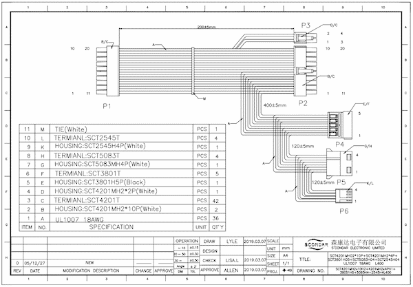
Every wire harness drawing relies on a precise hierarchy of lines, callouts, and symbols to denote how individual conductors bundle together within a protective sleeve or loom. Solid lines typically represent individual wires, while dashed or bracketed outlines indicate harness boundaries, multi-pin connectors, or splices. Understanding how these pathways interact with control components is thoroughly detailed in Relay and Component Wiring Diagrams, which break down the division between low-current control circuits and high-current load loops.
[Finding] — According to the National Fire Protection Association (NFPA), electrical failures and malfunctions consistently rank among the leading causes of residential and vehicular fires, underscoring the critical importance of accurate schematic interpretation and correct wiring practices.
Diagram Explanation and Key Components
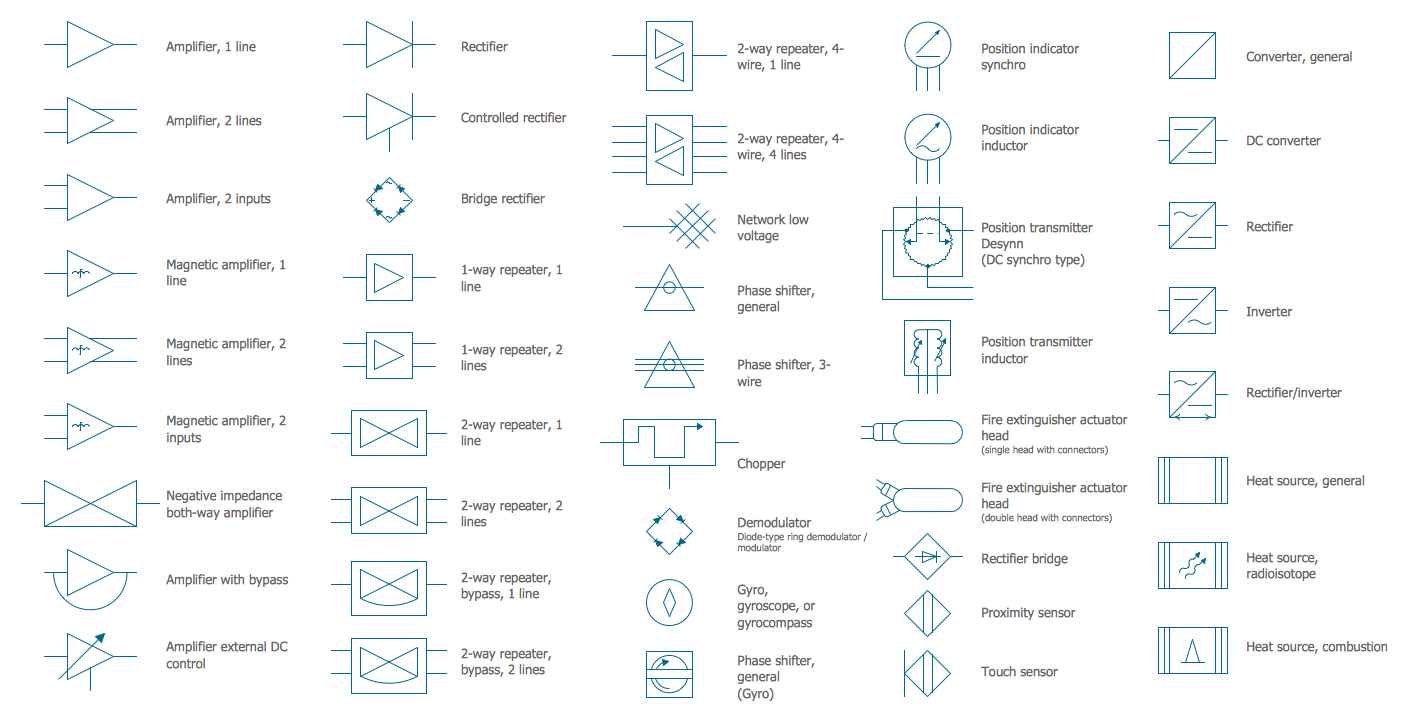
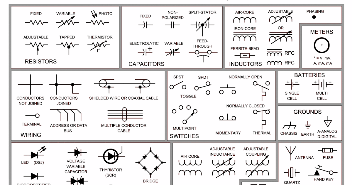
Reading wire harness drawing symbols requires recognizing the distinct shapes assigned to each physical component, such as resistors, capacitors, switches, fuses, and grounds. A zigzag line or rectangle designates a resistor, two parallel plates denote a capacitor, and an open or closed bridge indicates a mechanical switch. Fuses appear as a wavy line inside a rectangular box, signaling an overcurrent protection device designed to melt and break the circuit during a short circuit condition.
Color codes and terminal identification numbers add another layer of critical information to any schematic. Regional standards dictate wire color usage; for instance, North American automotive standards managed by the Society of Automotive Engineers (SAE) differ significantly from international standards and household codes regulated by the National Electrical Code (NEC) in the United States, the Canadian Electrical Code (CEC), BS 7671 in the United Kingdom, and AS/NZS 3000 in Australia. Cross-referencing these color designations prevents catastrophic miswirings during installation or repair.
Common Problems and Troubleshooting Methods
Systematic fault-finding begins with comparing the physical harness against the schematic symbols to isolate open circuits, high-resistance connections, short circuits to ground, and degraded splices. Technicians frequently encounter high-resistance faults caused by corrosion inside multi-pin connectors or fractured copper strands hidden beneath unbroken wire insulation. Relying blindly on visual inspections often misses these internal failures, making structured diagnostic measurements essential.
A methodical diagnostic process utilizes a digital multimeter to verify continuity, voltage drop, and resistance across specific symbol nodes mapped on the drawing. When tracing an intermittent fault within a complex bundle, technicians isolate sections of the harness by disconnecting junction blocks shown on the diagram. For further guidance on isolating erratic electrical behavior, consulting resources dedicated to Wiring Troubleshooting provides structured workflows for tracking down elusive voltage leaks and grounded circuits.
Practical Tips and Safety Considerations
Working with electrical systems demands rigorous adherence to safety protocols, proper tool selection, and correct wire sizing to prevent overheating and insulation failure. Before starting any hands-on intervention involving mains-voltage or high-current automotive circuits, technicians must de-energize the system, disconnect the vehicle battery or main breaker, and verify zero energy state using a calibrated voltage tester. Local regulations often require licensed electricians or qualified technicians for permanent household or industrial installations.
When modifying or repairing a wire harness, always match replacement wire gauge and insulation type to the original manufacturer specifications or applicable regional codes. Avoid improper splicing methods such as twisting wires together without solder or heat-shrink tubing, as these shortcuts introduce high resistance and moisture ingress. Utilizing proper crimping tools, weatherproof connectors, and abrasion-resistant loom ensures the repaired harness withstands vibration, thermal cycling, and environmental exposure over its operational lifespan.
Conclusion
Decoding wire harness drawing symbols bridges the gap between abstract engineering documentation and physical electrical repair. Committing standard schematic markers to memory empowers technicians to approach complex electrical architectures with confidence and precision. Prioritizing safety, verifying every circuit with testing instruments, and referencing foundational guides such as Wiring Diagram Basics ensures long-term reliability and professional-grade results across every electrical project.
Quick Wiring Specifications & Terminal Guide
| Component / Circuit | Standard Wire Gauge | Recommended Protection |
|---|---|---|
| Control & Trigger Signals | 18 – 20 AWG | 5A – 7.5A Inline Fuse |
| Standard Auxiliary Load | 14 – 16 AWG | 15A – 20A Circuit Breaker |
| Main Power Feed / Supply | 10 – 12 AWG | 30A – 40A Heavy-Duty Relay |
Images References