Introduction
A typical wiring diagram for a float switch illustrates the electrical connections required to automate fluid level control in residential, commercial, and industrial applications. Understanding this schematic is essential for operating sump pumps, bilge pumps, and tank-filling systems reliably. A float switch acts as a mechanical gatekeeper, using a buoyant tethered or vertical mechanism to open and close electrical contacts based on liquid levels. Mastering these diagrams prevents dry running of pumps, avoids catastrophic overflows, and ensures that control circuits integrate properly with high-voltage mains or low-voltage direct current power supplies. Proper interpretation of these schematics directly improves installation quality and reduces the risk of electrical shock or equipment burnout.
💡 Technical Key Takeaways:
- Core Focus: Diagnostic schematic and terminal connection layout for Typical Wiring Diagram For A Float Swithch.
- Target Scope: Field technicians, automotive DIYers, and residential/commercial electricians.
- Safety Rule: Always disconnect the primary power source/battery terminal and verify zero voltage with a multimeter before touching wires.
Core Concepts and Wiring Fundamentals
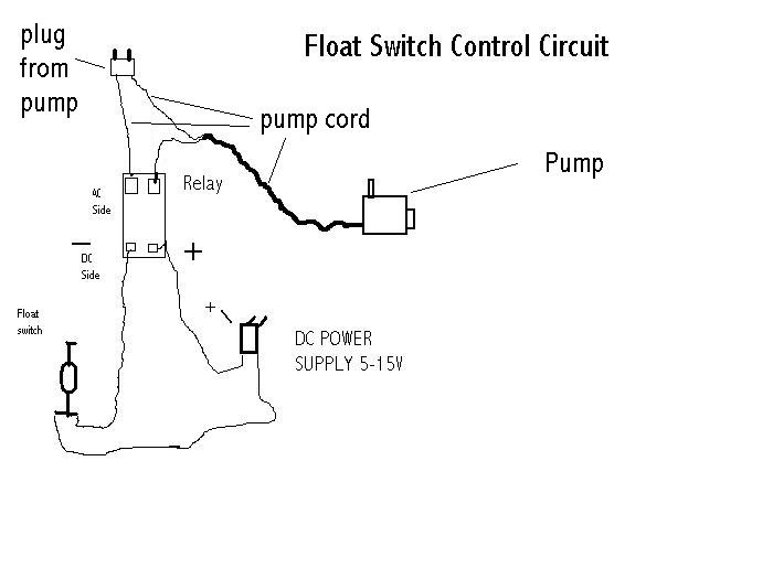
Float switches operate by utilizing internal gravity-actuated contacts, typically configured as Single-Pole Double-Throw (SPDT) switches that provide both Normally Open (NO) and Normally Closed (NC) pathways. In a standard control circuit, the switch interfaces between a power source and a load, such as a pump motor or an alarm panel. Direct switching of heavy pump loads through a small float switch often leads to premature contact welding, which necessitates the inclusion of an electromechanical relay or motor starter in the architecture.
Control circuits managing these devices rely on standardized wire routing, fuses for overcurrent protection, and secure terminal connections. Depending on the application, power may be delivered via a household alternating current (AC) circuit or a low-voltage direct current (DC) source found in automotive or marine environments. Regional electrical codes dictate specific wiring methods, such as utilizing watertight enclosures and appropriate cable insulation to withstand submersion and corrosive environments. Further foundational knowledge can be explored within Appliance and Device Wiring.
[Float switch failures in sump applications are frequently attributed to mechanical tether restriction or debris accumulation rather than electrical contact degradation, according to field maintenance data compiled by the Consumer Product Safety Commission] — CPSC
Diagram Explanation and Key Components
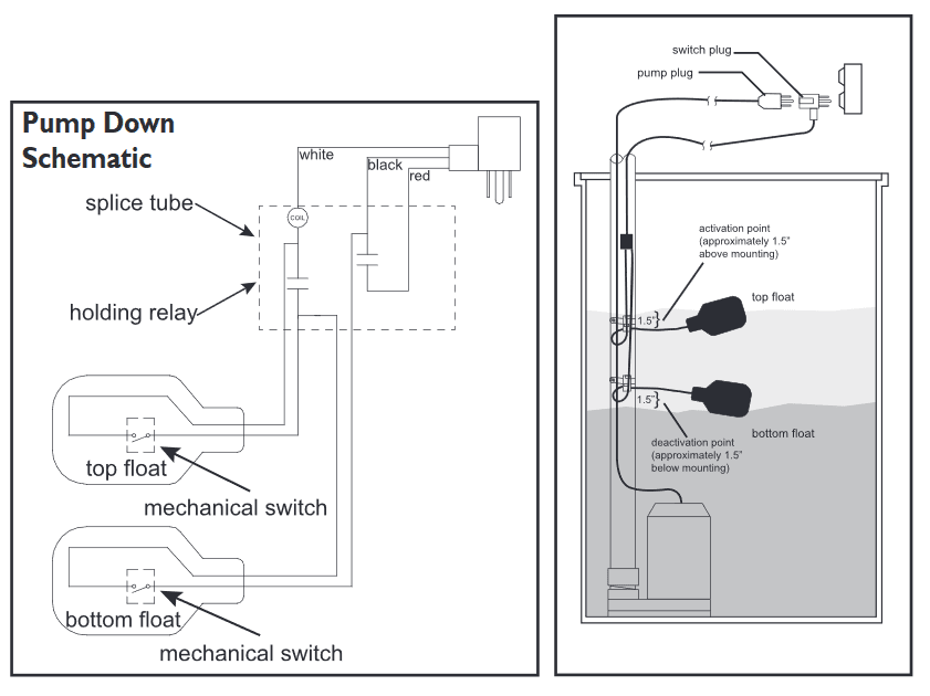
Reading a typical wiring diagram for a float switch requires recognizing standardized symbols for movable contacts, hinged levers, and terminal blocks. Schematics generally depict the switch in its resting or empty state, showing whether the internal contacts are open or closed before liquid immersion occurs. Lines on the diagram represent conductors, with line styles distinguishing between control voltage loops and heavy-duty load current pathways.
Color coding on wiring diagrams assists technicians in tracing circuits physically. In North American AC applications governed by the National Electrical Code (NEC/NFPA 70), hot conductors are often black or red, neutrals are white, and equipment grounding conductors are green or bare copper. Conversely, British standard BS 7671 uses brown for live, blue for neutral, and green-and-yellow for earth. The schematic maps these color designations directly to the float switch leads, incoming power supplies, and output terminals leading to the pump motor or indicator light.
Common Problems and Troubleshooting Methods
Systematic diagnosis of a malfunctioning float switch circuit begins with visual inspection and multimeter verification of continuity across the switch contacts. Typical faults involve open circuits caused by internal contact corrosion, seized mechanical pivots, or severed external cables from constant agitation in turbulent liquids. Intermittent operation often traces back to a compromised wire splice exposed to moisture or a blown control circuit fuse resulting from a shorted motor winding.
A structured diagnostic approach requires isolating the control circuit from the power source before performing resistance measurements. Technicians manually actuate the float while monitoring continuity with an ohmmeter to confirm whether the internal switch transitions correctly between states. If the switch passes bench testing, the focus shifts to verifying voltage drop across control relays and checking that terminal screws are torqued securely to prevent high-resistance connections. For broader fault-finding strategies applicable to these systems, consult resources on Wiring Troubleshooting.
Practical Tips and Safety Considerations
Mains-voltage float switch installations demand strict adherence to electrical safety protocols, including completely de-energizing the circuit and verifying zero energy state with a calibrated voltage tester prior to touching any terminals. Working on marine or automotive 12V/24V DC systems requires disconnecting the battery negative terminal to prevent accidental arcing. Technicians must always match wire gauge size to the maximum current draw of the connected load, utilizing marine-grade tinned copper wire in wet locations to resist oxidation.
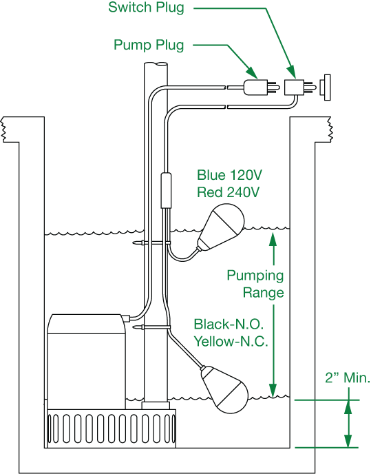
A common installation mistake involves failing to secure the tether cord adequately, which allows the cable to snag on plumbing pipes inside a basin. Mechanics and DIY installers should verify that the tether length provides a sufficient pumping range without placing undue mechanical strain on the cable jacket. Heat-shrink butt connectors with adhesive lining should be employed for any splices exposed to humidity to prevent moisture ingress. Where local jurisdiction dictates, installations involving fixed residential or commercial wiring must be performed or inspected by a licensed electrician to comply with regional safety standards such as the Canadian Electrical Code (CEC) or AS/NZS 3000 in Australia.
Conclusion
Interpreting a typical wiring diagram for a float switch empowers technicians and DIYers to install, maintain, and diagnose fluid level control systems with confidence. Recognizing symbol conventions, understanding the distinction between control loops and power loads, and respecting regional electrical standards ensures long-term operational reliability. Systematic troubleshooting methods isolate faults efficiently while minimizing safety risks. Additional schematics and component layouts can be reviewed through Relay and Component Wiring Diagrams to further expand technical proficiency in automated control systems.
Quick Wiring Specifications & Terminal Guide
| Component / Circuit | Standard Wire Gauge | Recommended Protection |
|---|---|---|
| Control & Trigger Signals | 18 – 20 AWG | 5A – 7.5A Inline Fuse |
| Standard Auxiliary Load | 14 – 16 AWG | 15A – 20A Circuit Breaker |
| Main Power Feed / Supply | 10 – 12 AWG | 30A – 40A Heavy-Duty Relay |
Images References