Ensuring your trailer’s lights and electrical systems work correctly is paramount for safety and legal compliance. The heart of this system often lies within the trailer wiring junction box. A clear understanding of the trailer wiring junction box diagram is essential for both initial setup and troubleshooting electrical issues. This article will break down the importance, benefits, structure, and interpretation of these diagrams, providing you with the knowledge to confidently handle your trailer’s wiring.
The trailer wiring junction box acts as a central hub where all the wires from your tow vehicle and the trailer converge and connect. Without a properly functioning system, brake lights, turn signals, running lights, and even auxiliary power (for things like interior lights or electric brakes) can be compromised. This not only creates a dangerous situation for you and other drivers but can also lead to hefty fines and legal repercussions. Therefore, mastering the ability to read and understand a trailer wiring junction box diagram is not just a helpful skill, but a necessary one for any trailer owner.
The key benefits of understanding your trailer wiring junction box diagram extend beyond simple functionality. First and foremost, it allows you to quickly diagnose and resolve electrical problems. Instead of blindly guessing, you can use the diagram to trace wires and identify potential faults, such as shorts, open circuits, or corroded connections. Secondly, it empowers you to perform your own maintenance and upgrades. Whether you’re adding new lights, installing a brake controller, or replacing damaged wiring, the diagram provides a roadmap for safe and effective modification. Finally, having this knowledge can save you significant money on professional repairs, as you can handle many common issues yourself.
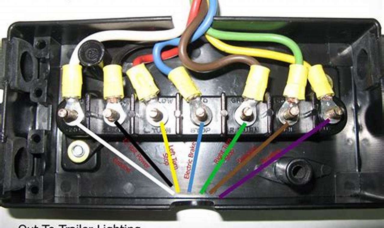
A typical trailer wiring junction box diagram is structured around a standardized color-coding system, which is crucial for correct wire identification. Common colors include: White (Ground), Brown (Tail/Running Lights), Yellow (Left Turn/Brake Light), Green (Right Turn/Brake Light), and Blue (Electric Brakes). The diagram will illustrate how these wires connect within the junction box, often represented by symbols or abbreviations. It will also indicate the corresponding pins on the trailer connector and the wiring connections to various components like lights and brakes. Diagrams may vary slightly depending on the trailer type and manufacturer, but the core color-coding and functional logic remain consistent.
Reading a trailer wiring junction box diagram involves several key steps. Start by identifying the trailer connector (usually a 4-way flat, 5-way flat, 6-way round, or 7-way round). Next, trace each wire from the connector to its corresponding terminal within the junction box. Pay close attention to the color-coding and ensure that the wires are connected as indicated on the diagram. If you are troubleshooting, use a multimeter to test the continuity and voltage of each wire to identify any breaks or shorts. Always disconnect the trailer from the tow vehicle before working on the wiring to prevent electrical shocks or damage to the system.
For additional tips, always use high-quality wiring connectors and terminals designed for automotive use. Ensure that all connections are clean, tight, and protected from moisture and corrosion. Use dielectric grease on the connectors to prevent corrosion. Label each wire with its corresponding function for easy identification in the future. If you are unsure about any aspect of the wiring, consult with a qualified automotive electrician. Understanding and utilizing a trailer wiring junction box diagram provides the knowledge and confidence to maintain your trailer’s electrical system safely and effectively. By mastering this skill, you ensure your trailer’s reliable performance and safe travels for years to come.
