Introduction
A trailer wiring 5 pin with fuse block, 2 relays and 118158 spilter constitutes an advanced custom towing electrical architecture designed to safely isolate vehicle lighting modules from high-draw or specialty trailer functions like hydraulic surge brake reverse lockouts. Modern vehicles utilizing pulse-width modulation or multiplexed computer lighting modules often suffer permanent electronic damage when directly connected to heavy auxiliary trailer loads. Integrating a dedicated auxiliary power distribution center junto with an electronic converter unit ensures reliable circuit protection and prevents fault codes from triggering on the tow vehicle dashboard. Mastering this specific configuration directly improves towing safety, eliminates erratic lighting behavior, and provides clean power distribution for auxiliary equipment.
💡 Technical Key Takeaways:
- Core Focus: Diagnostic schematic and terminal connection layout for Trailer Wiring 5 Pin With Fuse Block, 2 Relays And 118158 Spilter.
- Target Scope: Field technicians, automotive DIYers, and residential/commercial electricians.
- Safety Rule: Always disconnect the primary power source/battery terminal and verify zero voltage with a multimeter before touching wires.
Core Concepts and Wiring Fundamentals
Direct current 12-volt automotive electrical systems rely on complete circuits comprising a positive power feed, a dedicated load device, and a secure chassis ground path to return current back to the battery source. In standard towing applications, a basic 4-way flat plug handles tail, brake, and turn signals, whereas a 5-pin configuration adds a dedicated circuit specifically designated for reverse lights or surge brake lockout solenoids. Because standard vehicle reverse circuits cannot safely sustain the continuous current draw of a heavy magnetic brake release solenoid, engineers implement electromechanical switching devices known as relays. A relay uses a low-current trigger signal from the reverse light circuit to close an internal magnetic switch, allowing high-amperage current to flow directly from an independent fused power source straight to the trailer pin.
The inclusion of a dedicated auxiliary fuse block centralizes circuit protection, allowing each distinct branch to feature properly rated blade fuses matching the current-carrying capacity of the connected wire gauge. Vehicle-specific powered converters, such as the widely utilized Curt 118158 powered taillight converter, take raw braking and turn signals from separated vehicle stop-and-turn circuits and combine them into a single-wire standard system while drawing operating power directly from the vehicle battery rather than overloading factory lighting computers. Grounding integrity remains paramount across all components; painted or rusted frame attachment points introduce high resistance, which causes voltage drops, dim lighting, and intermittent relay chatter. Technicians frequently consult Vehicle Wiring Diagrams to trace factory integration points before mounting auxiliary fuse blocks and relay sockets near the rear cargo area.
According to the Society of Automotive Engineers (SAE) J2283 standards for trailer tow electrical interfaces, auxiliary power circuits must be protected by overcurrent devices sized strictly to match the minimum ampacity rating of the smallest conductor in the circuit to prevent thermal overload and wiring harness degradation. — SAE International
Diagram Explanation and Key Components
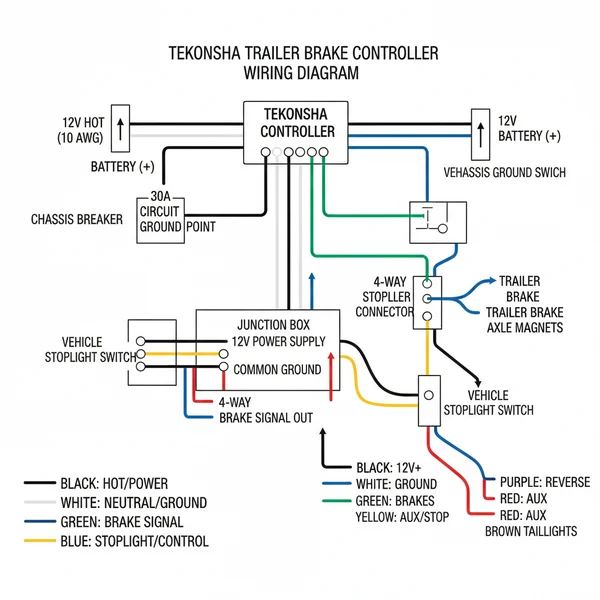
Reading a technical schematic for a trailer wiring 5 pin with fuse block, 2 relays and 118158 spilter requires identifying standardized symbols representing power distribution blocks, mechanical switches, electronic logic converters, and multi-pin terminal connectors. The electronic converter acts as an active signal translator, utilizing power from a fused battery feed to replicate vehicle input commands onto output lines without drawing substantial current through sensitive factory body control modules. Relay terminals are universally designated by standardized numbering conventions, where terminal 30 connects to the unfused or fused battery supply, terminal 87 delivers output power to the load, terminal 85 receives the low-current activation ground or trigger, and terminal 86 receives the switch control power.
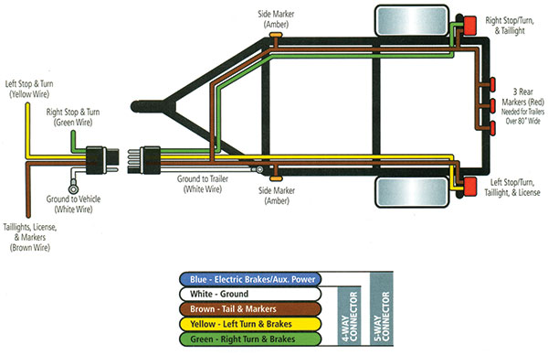
Color coding on standard North American trailer harnesses typically designates white as the main system ground, brown as running and taillights, yellow as the left turn and stop signal, green as the right turn and stop signal, and blue or sometimes black as the auxiliary 5th pin reverse or brake lockout function. European or Australian installations governed by regional standards may utilize entirely different color arrangements, necessitating careful multimeter verification prior to pin termination. The physical fuse block houses modular fuses that protect both the converter module feed and the individual relay power feeds against downstream short circuits. Understanding how these distinct components interface requires careful study of Relay and Component Wiring Diagrams to ensure correct terminal placement and eliminate cross-circuit feedback.
Common Problems and Troubleshooting Methods
Systematic diagnostic testing for a trailer wiring 5 pin with fuse block, 2 relays and 118158 spilter begins with verifying primary battery supply voltage at the main input terminals of the auxiliary fuse block using a high-impedance digital multimeter. A frequent real-world failure point involves corroded relay socket terminals caused by moisture intrusion inside rear quarter panels or undercarriage mounting locations, which results in intermittent operational loss of the 5th pin reverse function. Technicians must visually inspect all inline blade fuses for thermal discoloration or fractured fusible links, replacing blown fuses only after isolating the underlying short circuit condition. When trailer lights illuminate faintly or flicker erratically during vehicle braking maneuvers, the primary diagnostic procedure requires checking the resistance between the main white harness ground wire and clean bare vehicle chassis metal.
Testing the active converter module involves probing input wires while an assistant operates vehicle controls to confirm that command signals reach the module, followed by checking output wires to ensure the internal solid-state switches are successfully passing voltage. If inputs register correctly but outputs remain dead, internal module failure or an interrupted primary power supply feed is indicated. Mechanics facing complex diagnostic scenarios often reference structured troubleshooting guides found within Wiring Troubleshooting resources to isolate intermittent electrical faults methodically without unnecessary component replacement.
Practical Tips and Safety Considerations
Implementing a reliable towing electrical modification demands adherence to professional installation practices, including disconnecting the negative vehicle battery terminal before stripping insulation, crimping terminals, or mounting hardware to prevent accidental arcing. All electrical connections exposed to exterior weather elements require heat-shrink butt connectors lined with thermoplastic adhesive to seal out moisture, salt, and road grime effectively. Wire gauges must be selected appropriately based on total circuit length and anticipated electrical load, utilizing heavier 10-gauge or 12-gauge wire for primary power feeds and lighter 16-gauge or 18-gauge wire for low-draw signal trigger circuits. A common installation error involves routing wiring harnesses too close to hot vehicle exhaust pipes or sharp sheet metal edges without protective split-loom tubing or rubber grommets, which inevitably leads to chafing and catastrophic short circuits over time. Always verify local regional regulations and consult a qualified automotive technician where complex multiplexed body computer integrations require specialized diagnostic programming.
Conclusion
Properly installing and maintaining a trailer wiring 5 pin with fuse block, 2 relays and 118158 spilter safeguards sensitive vehicle electronics while ensuring dependable operation of auxiliary trailer brake lockouts and specialty lighting systems. Diligent attention to secure chassis grounding, correct fuse sizing, and weatherproof terminal connections eliminates common roadside failures and prevents expensive electrical damage to modern tow vehicles. Continuing education regarding mobile electrical distribution systems remains vital for both professional technicians and dedicated DIY enthusiasts seeking safe, long-lasting towing performance. For additional insights into auxiliary circuit designs and related systems, review Wiring Diagram Basics to strengthen fundamental interpretation skills.
Quick Wiring Specifications & Terminal Guide
| Component / Circuit | Standard Wire Gauge | Recommended Protection |
|---|---|---|
| Control & Trigger Signals | 18 – 20 AWG | 5A – 7.5A Inline Fuse |
| Standard Auxiliary Load | 14 – 16 AWG | 15A – 20A Circuit Breaker |
| Main Power Feed / Supply | 10 – 12 AWG | 30A – 40A Heavy-Duty Relay |
Images References