Effective network cabling hinges on a clear understanding of structured wiring standards. Proper cable termination ensures consistent and reliable data transmission, preventing frustrating network slowdowns and connectivity issues. Mastering the industry-standard wiring conventions is a cornerstone of effective network administration and ensures smooth communication across various devices. Neglecting these standards can lead to significant performance degradation and troubleshooting headaches.
Understanding the fundamental wiring configurations equips one with the ability to troubleshoot network problems efficiently. It empowers individuals to diagnose connectivity issues rapidly and implement effective solutions, whether in a home network or a complex office environment. Furthermore, it facilitates the creation of custom cable solutions tailored to specific network requirements, offering flexibility and optimization not achievable with pre-made cables. Correct wiring minimizes signal loss and interference, leading to improved network stability and speed.
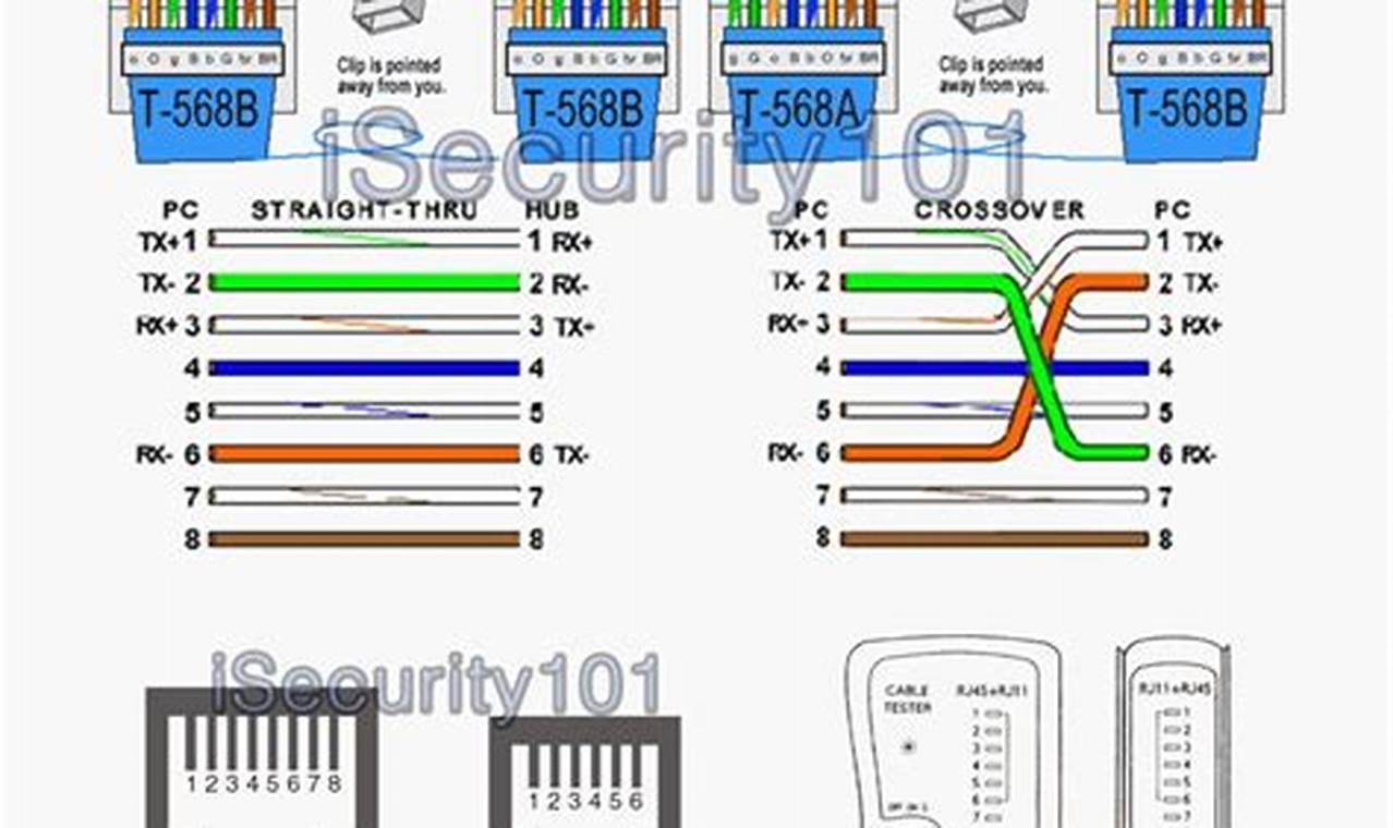
Network cable wiring configurations employ a twisted-pair design, aiming to minimize electromagnetic interference. Each wire within the cable corresponds to a specific pin on the RJ45 connector. Diagrams illustrate the sequential arrangement of these wires, typically color-coded for easy identification. Following the diagram, the eight wires are inserted into the RJ45 connector, ensuring that each wire sits precisely on its designated pin. The connector is then crimped to secure the wires and establish solid electrical connections.
To apply a specific wiring standard, begin by stripping the outer jacket of the network cable, carefully exposing the twisted pairs. Untwist the pairs and arrange the individual wires in the order specified by the chosen configuration, referencing the detailed diagram. Insert the wires into the RJ45 connector, ensuring each wire reaches the end of the connector and maintains the correct order. Use a crimping tool to firmly secure the connector to the cable, creating a robust and reliable termination. Test the connection with a cable tester to verify proper wiring and signal continuity.
For optimal network performance, consider the cable type and length limitations. Category 5e and Category 6 cables are the most common choices for Ethernet networks. Adhering to a consistent wiring scheme across an entire network is critical for simplifying troubleshooting and preventing errors. Online resources such as cable manufacturer websites and networking forums offer valuable supplementary information and guidance on advanced cabling techniques and best practices.
Proficiency in structured network wiring provides a solid foundation for building and maintaining robust and reliable network infrastructure. It empowers individuals to take control of their network connectivity, troubleshoot issues effectively, and optimize performance. Continue expanding your wiring expertise by exploring additional resources and practical examples on readwires.com.
