Introduction
Water pump pressure switch wiring involves connecting an automatic electromechanical control device to a household alternating current supply and a motorized pump to maintain consistent plumbing pressure. Mastering how to wire water pump pressure switch diagram 120v ensures reliable operation in residential well systems and booster setups while preventing severe electrical hazards. This configuration is widely used in domestic water delivery applications. Understanding the layout improves installation quality, prevents equipment damage, and ensures precise troubleshooting accuracy.
💡 Technical Key Takeaways:
- Core Focus: Diagnostic schematic and terminal connection layout for How To Wire Water Pump Pressure Switch Diagram 120V.
- Target Scope: Field technicians, automotive DIYers, and residential/commercial electricians.
- Safety Rule: Always disconnect the primary power source/battery terminal and verify zero voltage with a multimeter before touching wires.
Core Concepts and Wiring Fundamentals
A pressure switch acts as a line-voltage controller that opens and closes internal contacts based on hydraulic pressure thresholds. When system pressure drops below the cut-in threshold, internal spring-loaded contacts close to energize the pump motor. When pressure reaches the cut-out threshold, the contacts snap open to interrupt the electrical circuit.
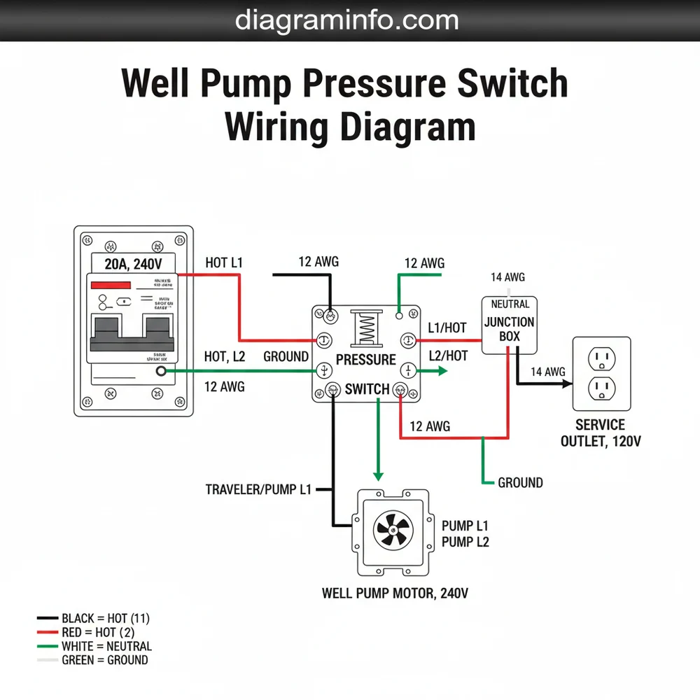
In a standard 120-volt household setup, the circuit carries line voltage through the switch directly to the pump motor. Single-phase 120V circuits typically utilize a hot wire, a neutral wire, and a bare or green ground wire. The pressure switch features two pairs of terminal screws housed beneath a removable plastic cover. Incoming supply power attaches to one side, while outgoing motor leads connect to the opposite side. A thorough understanding of Home Electrical Wiring Diagrams is essential before attempting any physical connections.
[Electric shock and arc flash remain primary hazards when servicing household water systems] — [Electrical Safety Foundation International (ESFI)]
Diagram Explanation and Key Components
Reading a schematic for how to wire water pump pressure switch diagram 120v requires recognizing specific electromechanical symbols and regional color conventions. In North America under the National Electrical Code (NEC/NFPA 70), the hot wire is typically black, the neutral is white, and the ground is bare copper or green. In the UK and Europe (BS 7671), the hot wire is brown, the neutral is blue, and the ground is green-and-yellow. In Australia and New Zealand (AS/NZS 3000), the active wire is brown, neutral is light blue, and earth is green-and-yellow.
The wiring diagram illustrates a simple series loop. Power enters the pressure switch housing through a cable connector, terminating at the line-side upper terminals. The lower terminals, designated as load-side connections, route the switched power onward to the water pump motor. Ground wires from both the supply cable and the pump motor cable must bond securely to the green grounding screw on the metal switch body. Reviewing Wiring Diagram Basics provides additional clarity on interpreting schematic symbols and line types.
Common Problems and Troubleshooting Methods
Systematic fault-finding begins by verifying voltage presence with a calibrated multimeter while observing strict safety protocols to avoid electric shock. Typical issues include burned contact points, stuck diaphragms, and loose terminal screws caused by constant mechanical vibration from the pump motor. A pump that fails to start when pressure drops often indicates either an open circuit across the switch contacts or a tripped circuit breaker.
Diagnosis involves isolating the circuit, de-energizing the system, and testing continuity across the switch terminals with the pump disconnected. Closed contacts should show near-zero resistance, while open contacts show infinite resistance. If the contacts remain welded shut due to an electrical surge, the switch must be replaced entirely. Further diagnostic strategies for related equipment are detailed in Wiring Troubleshooting to help isolate whether the fault lies in the switch, wiring, or motor.
Practical Tips and Safety Considerations
Mains-voltage and high-current installations demand rigorous adherence to safety standards and regional regulations. Always de-energize the circuit at the main breaker panel and verify zero voltage with a reliable voltage tester before touching any internal components. Local law often requires a licensed electrician or qualified technician to perform permanent household wiring modifications.
Field experience reveals that failing to use proper cable clamps on the pressure switch knockouts is a frequent installation mistake. Unsecured cables allow moisture ingress or mechanical strain, which can pull wires loose from their terminal screws. Always match wire gauge to the total amperage draw of the pump motor and the specific circuit breaker rating, consulting local codes or manufacturer specifications for exact sizing requirements.
Conclusion
Proper installation of a 120V water pump pressure switch safeguards the entire domestic water delivery system against electrical failure and premature motor wear. Adhering to manufacturer guidelines, verifying correct wire color codes, and maintaining secure terminal connections guarantee long-term operational safety. Competent execution of these wiring tasks requires patience, methodical testing, and respect for line voltage. For further exploration of related control systems, consult Relay and Component Wiring Diagrams.
Quick Wiring Specifications & Terminal Guide
| Component / Circuit | Standard Wire Gauge | Recommended Protection |
|---|---|---|
| Control & Trigger Signals | 18 – 20 AWG | 5A – 7.5A Inline Fuse |
| Standard Auxiliary Load | 14 – 16 AWG | 15A – 20A Circuit Breaker |
| Main Power Feed / Supply | 10 – 12 AWG | 30A – 40A Heavy-Duty Relay |
Images References