Introduction
A gm 3 wire alternator diagram maps out the internal regulation and external charging circuit for classic and modern General Motors vehicle electrical systems, detailing how mechanical rotation converts into regulated direct current power. Mastering this specific configuration matters immensely for automotive restoration, custom engine swaps, and general electrical diagnostics across North American, European, and Australian service bays. Understanding these circuits prevents costly component failures, protects sensitive onboard electronics from voltage spikes, and ensures reliable battery replenishment. Accurate comprehension of vehicle charging layouts directly improves diagnostic speed, reduces unnecessary parts replacement, and maintains system integrity. For further exploration of mobile electrical configurations, consult specialized resources such as Vehicle Wiring Diagrams.
💡 Technical Key Takeaways:
- Core Focus: Diagnostic schematic and terminal connection layout for Gm 3 Wire Alternator Diagram.
- Target Scope: Field technicians, automotive DIYers, and residential/commercial electricians.
- Safety Rule: Always disconnect the primary power source/battery terminal and verify zero voltage with a multimeter before touching wires.
Core Concepts and Wiring Fundamentals
The three-wire General Motors charging layout typically utilizes a heavy-duty battery output stud along with a dual-terminal plastic connector plug, separating power delivery from excitation control. Direct current flows from the internal diodes through the main stud to the battery via a high-amp fusible link or inline fuse. Meanwhile, the control plug manages internal voltage sensing and rotor excitation through dedicated circuits commonly labeled by terminal identifiers. In standard legacy designs governed by Society of Automotive Engineers standards, these connector pins serve distinct operational functions that dictate overall output behavior.
Terminal one handles the initial excitation current, often running through an indicator dashboard lamp or resistor wire to supply a low-amperage turn-on signal. Terminal two serves as the voltage sensing wire, directly monitoring system electrical pressure at a remote junction point or fuse panel rather than measuring strictly at the alternator output stud. This remote sensing feature compensates for natural voltage drops across the main charging cable, ensuring the battery receives the correct charging potential under heavy accessory loads. Proper routing and clean connections along these low-current pathways remain vital for correct voltage regulation.
When working with automotive charging systems, always disconnect the negative battery cable before servicing terminals to prevent accidental short circuits or high-current sparks. Regional variations in aftermarket harnesses or older conversions may employ different wire colors, necessitating careful continuity testing rather than relying solely on visual insulation shades. Detailed studies on auxiliary control setups can be reviewed further under Relay and Component Wiring Diagrams.
[Finding] — Automotive electrical faults, particularly those involving corroded alternator sense circuits and high-resistance grounds, account for a substantial percentage of premature battery failures reported by the Consumer Product Safety Commission (CPSC) and automotive service associations.
Diagram Explanation and Key Components
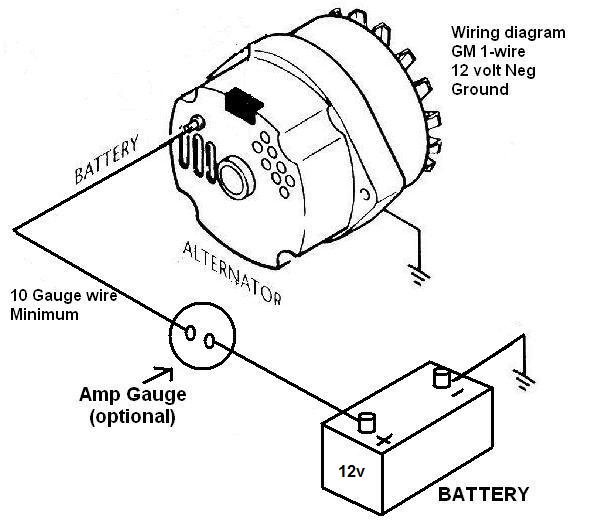
Reading a gm 3 wire alternator diagram requires recognizing standardized schematic symbols for diodes, regulators, windings, and fusible links. The main output wire, typically colored red or black depending on the specific model year and regional aftermarket kit, connects directly to the positive battery post or starter solenoid main terminal. The plastic connector housing locks into the side of the housing, featuring distinct terminal cavities marked by embossed letters or pin positions.
In a standard SI-series layout, the terminal connected to the indicator lamp is designated as the ignition feed, providing a path for initial magnetic field creation within the rotor assembly. Once the rotor spins fast enough, the internal stator generates enough self-sustaining voltage to match the dashboard feed, turning off the charging warning light by balancing the electrical potential on both sides of the bulb. The second terminal, functioning as the voltage reference, connects to an active 12-volt source within the vehicle harness to give the internal solid-state regulator an accurate reading of system demand.
Schematics utilize specific line weights to differentiate between heavy-gauge power feeds and fine-gauge control lines. Solid lines represent physical copper conductors, while dashed lines often indicate internal regulator pathways or optional external resistor loops. Technicians must trace each line carefully to verify that external jumper modifications or custom engine harnesses have not bypassed essential safety links or warning indicators.
Common Problems and Troubleshooting Methods
Systematic diagnostic testing for a failing charging layout involves checking voltage drops, continuity, and output ripple using a digital multimeter rather than relying on guesswork. A common field observation involves a vehicle that runs but fails to charge the battery adequately, frequently caused by an open circuit in the excitation wire or a blown dashboard indicator bulb. Without that initial excitation current, self-exciting alternators often fail to “turn on” until the engine reaches a high rotational speed.
Begin the diagnostic process by verifying battery voltage with the engine off, which should read approximately 12.6 volts on a healthy, fully charged 12V DC system. Start the engine and measure across the battery terminals again; a properly functioning charging circuit should display between 13.5 and 14.8 volts. If the reading remains at static battery voltage, inspect the main output wire for continuity and check the integrity of the fusible link. Next, disconnect the plug and verify that battery voltage is present at the voltage sense terminal with the ignition switch in the run position.
If voltage is missing at the control connector, trace the harness back to the ignition switch or fuse block to locate open circuits, damaged insulation, or corroded terminal pins. High resistance in the ground path between the alternator housing and the engine block can also prevent proper charging, making a voltage drop test across the negative circuit an essential diagnostic step. For systematic approaches to tracking down elusive electrical faults, reference the guides found in Wiring Troubleshooting.
Practical Tips and Safety Considerations
Best practices for servicing vehicle electrical systems demand strict adherence to safety protocols, correct wire sizing, and proper mechanical torque on all high-current fasteners. Always disconnect the battery negative terminal before tightening or removing the main alternator output nut to prevent accidental wrench grounding against the engine block. Never disconnect the battery while the engine is running to test the alternator, as this can generate massive voltage spikes that instantly destroy sensitive onboard computers and solid-state diodes.
Wire gauge selection remains critical when repairing or modifying charging harnesses, especially for the main output cable feeding high-amperage accessories. Utilizing undersized wire creates excessive heat, voltage drop, and potential fire hazards. Secure all harness runs away from exhaust manifolds, sharp sheet metal edges, and moving pulleys using insulated clamps and high-temperature loom protection. Following structured guidelines from recognized bodies like the Society of Automotive Engineers ensures long-term reliability and compliance with professional standards.
Conclusion
Mastering the layout and diagnostic workflow of a gm 3 wire alternator diagram empowers technicians and enthusiasts to resolve complex charging issues with confidence and precision. Thorough understanding of excitation circuits, voltage sensing lines, and main power paths transforms chaotic electrical work into a systematic process. Prioritizing safety, proper connection hygiene, and accurate multimeter testing prevents recurring failures and protects vehicle electronics. For further reference on underlying schematic rules and foundational layouts, review the principles outlined in Wiring Diagram Basics.
Quick Wiring Specifications & Terminal Guide
| Component / Circuit | Standard Wire Gauge | Recommended Protection |
|---|---|---|
| Control & Trigger Signals | 18 – 20 AWG | 5A – 7.5A Inline Fuse |
| Standard Auxiliary Load | 14 – 16 AWG | 15A – 20A Circuit Breaker |
| Main Power Feed / Supply | 10 – 12 AWG | 30A – 40A Heavy-Duty Relay |
Images References