Effective network infrastructure hinges on precise and reliable cabling. Understanding how data cables are terminated into their respective receptacles is crucial for ensuring optimal network performance and reliability. Properly connected cables ensure seamless data transmission, reducing the risk of connectivity issues and downtime. A solid grasp of cabling configurations enhances practical electrical skills and promotes overall network safety. Incorrectly wired connections can lead to network degradation or even hardware damage.
Mastering the principles of network cabling connection diagrams allows for efficient troubleshooting of network problems, enabling faster identification and resolution of cabling-related issues. This knowledge supports the creation of safer and more reliable network installations, minimizing potential hazards and ensuring compliance with industry standards. Individuals can confidently plan and execute network cabling projects, from small home networks to larger office environments. Accurate interpretation and application of these diagrams also reduce the likelihood of costly errors and rework.
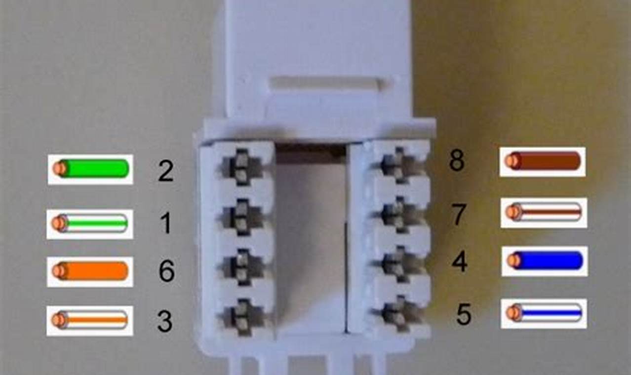
A typical connection diagram illustrates the arrangement of wires within a receptacle, depicting the color-coded wires and their corresponding terminals. Symbols represent the various components, such as the receptacle itself and the individual conductors. The diagram clearly shows the sequence in which the wires must be connected, often following either the T568A or T568B standard. These standards dictate the specific color sequence of the wires, and adherence to one standard throughout a network is essential for maintaining consistent performance.
Interpreting and applying a network cable termination diagram involves carefully matching each wire to its designated terminal within the receptacle. First, identify whether the diagram specifies the T568A or T568B standard. Prepare the cable by stripping the outer jacket to expose the individual wires. Arrange the wires in the correct color order as indicated by the diagram. Trim the wires to a uniform length and insert them into the receptacle, ensuring each wire is fully seated. Use a crimping tool to secure the wires in place, creating a solid and reliable connection. Test the connection with a cable tester to verify its integrity and ensure proper signal transmission.
Beyond basic connection techniques, consider the impact of cable length and environmental factors on network performance. Minimize cable bends and avoid running cables near sources of electromagnetic interference. Utilize appropriate cable management practices to maintain a clean and organized network infrastructure. For further information and practice, consult industry-standard networking guides and online resources that offer detailed cabling tutorials and diagrams. Experimenting with different cable termination tools and techniques can also improve proficiency and confidence.
The ability to accurately interpret and apply network cable connection diagrams is fundamental to establishing and maintaining robust network infrastructure. By mastering these diagrams, individuals can enhance their troubleshooting skills, improve the safety of network installations, and confidently undertake cabling projects. Further exploration of online resources and practical experimentation will solidify understanding and promote continued improvement in network cabling expertise. Consider exploring other resources on wiring and network configurations to expand your knowledge.
