Introduction
Mastering basic electrical wiring for beginners serves as the fundamental gateway to safely installing, maintaining, and repairing electrical circuits across automotive, residential, and industrial applications. Understanding these core principles matters because improper connections lead to equipment failure, intermittent electrical gremlins, severe fire hazards, and personal injury. This skill set applies directly to automotive 12V/24V DC systems, household AC circuits, internal appliance controls, and complex low-voltage networks. Approaching electrical work with structured knowledge improves troubleshooting accuracy, ensures code-compliant installations, and protects both the technician and the end user from preventable hazards.
💡 Technical Key Takeaways:
- Core Focus: Diagnostic schematic and terminal connection layout for Basic Electrical Wiring For Beginners.
- Target Scope: Field technicians, automotive DIYers, and residential/commercial electricians.
- Safety Rule: Always disconnect the primary power source/battery terminal and verify zero voltage with a multimeter before touching wires.
Core Concepts and Wiring Fundamentals
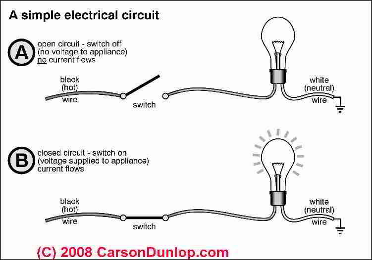
Electricity flows in a complete closed loop driven by voltage, impeded by resistance, and measured in current, requiring a stable power source, a continuous conductor path, and a load to perform work. Conductors are typically made of copper or aluminum wire, sized according to ampacity limitations, which define the maximum current a wire can carry safely without exceeding its temperature rating. Insulators shield these conductors to prevent accidental short circuits between adjacent wires or chassis ground points.
Direct current systems rely on positive supply lines and dedicated chassis or frame grounds to complete the circuit path. Alternating current household systems utilize hot conductors carrying current from the source, neutral conductors returning current back to the source, and green or bare copper equipment grounding conductors for fault protection. Circuit protection devices, including fuses and circuit breakers, interrupt excessive current flow during overloads or short circuits to safeguard the wiring harness and connected equipment.
Control devices such as switches interrupt the flow of current manually, while electromechanical relays use a low-current control circuit to switch a high-current load circuit. Connectors and terminals join wires mechanically and electrically, requiring proper crimping or soldering techniques to prevent high-resistance joints that generate destructive heat over time. For deeper exploration of how these parts interact, reference Relay and Component Wiring Diagrams for detailed control logic configurations.
Electrical faults and improper installations remain a leading cause of residential fires and equipment failures according to reports from the National Fire Protection Association (NFPA). — NFPA 70 National Electrical Code
Diagram Explanation and Key Components
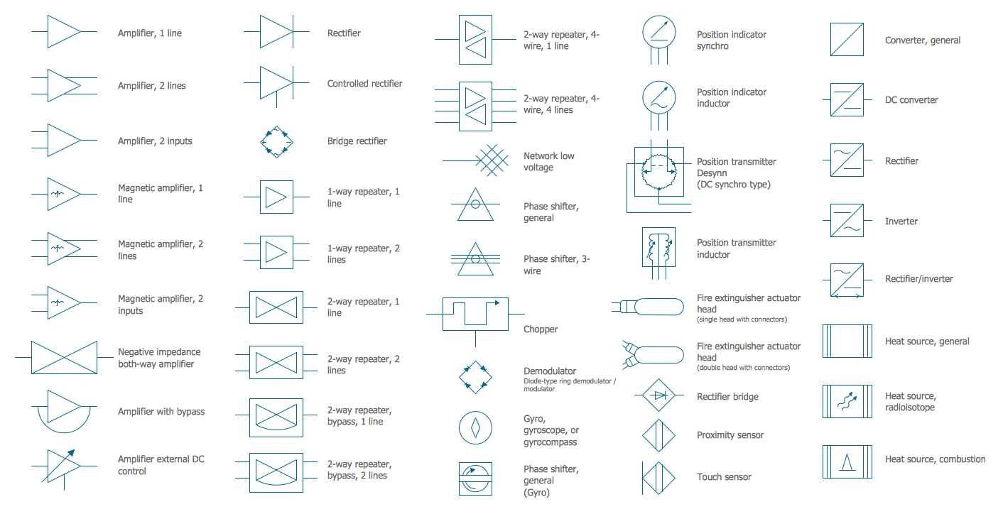
Reading electrical schematics requires translating standardized symbols, line types, and alphanumeric codes into a mental model of physical circuit operation. Schematics use straight lines to represent conductors and specialized geometric symbols to denote switches, resistors, fuses, grounds, and loads. Solid lines typically indicate primary power circuits, while dashed or dotted lines signify control loops, shielded cables, or mechanical linkages between components.
Color coding schemes vary significantly by region and application. In North American residential construction governed by the NEC (National Electrical Code) or CEC (Canadian Electrical Code), hot wires are typically black or red, neutrals are white or gray, and grounds are green or bare. Conversely, European and Australian systems governed by BS 7671 or AS/NZS 3000 employ brown for live, blue for neutral, and green-yellow for protective earth. Automotive DC systems utilize distinct color conventions set by standards such as SAE, where red usually denotes battery positive, black or brown denotes ground, and various striped combinations identify specific switched accessory lines.
Tracing a diagram starts at the power source, follows the active path through switches and protection devices, passes through the operational load, and finishes at the return path or ground symbol. For a broader foundational approach to decoding these blueprints, review the concepts outlined in Wiring Diagram Basics to recognize standard schematic conventions quickly.
Common Problems and Troubleshooting Methods
Systematic fault-finding relies on logical isolation of open circuits, short circuits, high-resistance connections, and ground faults using a digital multimeter or test light. An open circuit occurs when a break in the conductor stops current flow entirely, resulting in zero voltage drop across the load and infinite resistance on a meter. A short circuit happens when a hot conductor touches a ground or neutral path unintentionally, causing immediate fuse blowing or breaker tripping due to massive current spikes.
High-resistance faults, often caused by corrosion, loose terminal screws, or frayed wire strands, allow limited voltage to pass but restrict current, causing components to operate sluggishly or connectors to overheat. A methodical diagnostic workflow begins by verifying the power source, checking the fuse or circuit protection device, inspecting physical connector integrity, and measuring voltage drops across individual circuit segments rather than guessing at component replacements.
Field observations indicate that a high percentage of intermittent electrical failures stem from neglected ground connections rather than failed components. Corrosion under a bolted chassis ground or a loose star washer introduces intermittent resistance that defies simple static testing. Technicians seeking specialized diagnostic routines can consult Wiring Troubleshooting for advanced step-by-step isolation procedures.
Practical Tips and Safety Considerations
Prioritizing safety means always de-energizing circuits, verifying zero energy state with a calibrated meter, and disconnecting vehicle batteries before performing any physical wiring modifications. Local regulations dictate strict compliance standards, such as NEC/NFPA 70 in the US, the CEC in Canada, BS 7671 in the UK, and AS/NZS 3000 in Australia. When local law mandates professional certification, all mains-voltage installations or complex high-current modifications must be executed by a licensed electrician or qualified technician.
Proper tool selection is critical; insulated hand tools rated for electrical work, precise wire strippers that avoid nicking copper strands, and ratchet-action crimpers ensure mechanically sound connections. Heat-shrink tubing with adhesive lining provides superior environmental sealing over simple electrical tape, preventing moisture ingress and subsequent corrosion in exposed wiring environments. Avoid bundling signal cables directly alongside high-current power lines to eliminate electromagnetic induction and signal noise interference.
Conclusion
Building competency in basic electrical wiring for beginners transforms complex electrical systems from mysterious hazards into structured, manageable networks. Thorough understanding of circuit fundamentals, schematic symbols, and methodical diagnostic techniques empowers practitioners to execute clean installations and resolve electrical faults safely. Continuous adherence to regional safety standards and proper tool usage ensures long-term reliability and personal protection across every electrical project.
Quick Wiring Specifications & Terminal Guide
| Component / Circuit | Standard Wire Gauge | Recommended Protection |
|---|---|---|
| Control & Trigger Signals | 18 – 20 AWG | 5A – 7.5A Inline Fuse |
| Standard Auxiliary Load | 14 – 16 AWG | 15A – 20A Circuit Breaker |
| Main Power Feed / Supply | 10 – 12 AWG | 30A – 40A Heavy-Duty Relay |
Images References